Electric Motor
Current turned into rotation
Plate
- 1Field magnet
- 2Armature winding
- 3Commutator
- 4Brush
- 5Shaft and pulley
- 6Battery
Anatomy
Loading the figure…
An electric motor turns current into rotation: a coil carrying current between magnet poles is pushed sideways, and a commutator or a rotating field keeps that push acting in one direction. Moritz Jacobi's motor of 1834 delivered far more power than any before it, and motor-driven systems now use about half the world's electricity.
What it is
An electric motor turns electric current into rotation. It drives fans, pumps, lifts, trams and machine tools. The Electric Motor Systems Platform of the IEA’s 4E programme estimates that motor-driven systems used about 53% of the world’s electricity in 2023.
The plate shows a battery-fed direct-current motor of the late nineteenth century.
How it works
A wire carrying current inside a magnetic field is pushed sideways, at right angles to both the current and the field. In a coil set between two poles, the two long sides carry current in opposite directions, so one side is pushed up and the other down, and the coil turns.
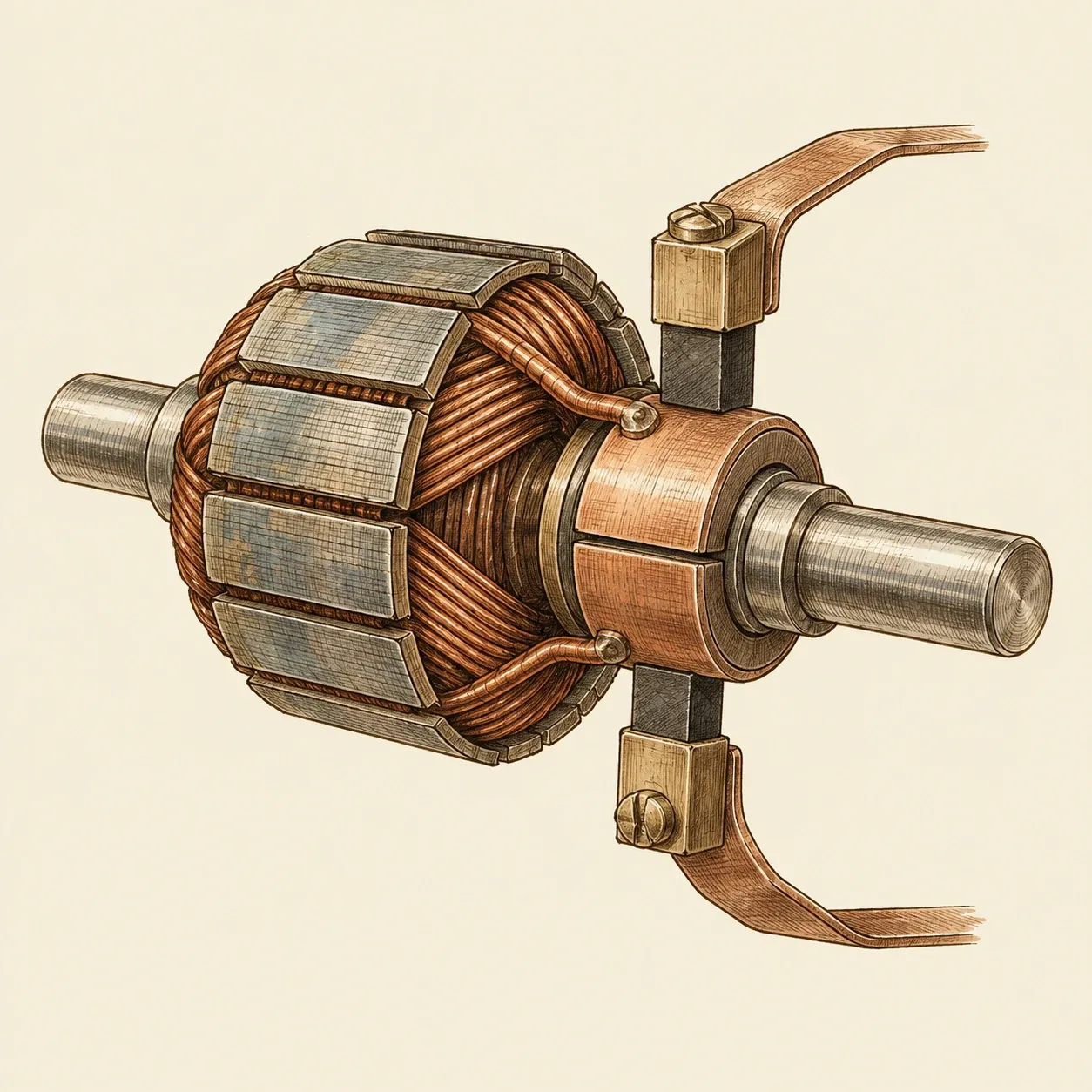 A two-part commutator: the brushes swap halves every half turn.
Left alone, the coil would swing until its plane stood square to the field, rock a few times and stop there. The commutator prevents this. It is a ring on the shaft cut into insulated segments, each wired to the coil, and two fixed brushes rub on it to bring in the current. In the simplest, two-segment form, every half turn the brushes pass to the other segment, the current in the coil reverses, and the torque keeps pointing the same way.
Working armatures carry many coils spread around an iron drum, each joined to its own segments, so the torque stays even. The iron is stacked from thin insulated sheets, because a solid core would carry eddy currents that waste power as heat. The field comes from permanent magnets in many small motors and from electromagnets in most machines of the nineteenth century, like the one on the plate.
A spinning armature also works as a generator. Its coils produce a voltage that opposes the supply, called back-EMF, which grows with speed. At start-up there is none, so the current can be many times its running value. As the motor speeds up, the back-EMF rises and the current falls until the torque matches the load. Turned by hand, with its field magnetised and a load connected, the same machine sends current out: a motor and a generator are one device used in opposite directions.
Induction motors, fed with alternating current, have no commutator. Fixed windings carrying currents out of step create a rotating magnetic field. It induces currents in the copper or aluminium bars of the rotor, which turns a little slower than the field.
How to build
The classroom motor needs one 1.5 V cell (size D or AA), about a metre of enamelled copper wire 0.5 to 0.8 mm thick, two large paper clips, a ceramic or neodymium disc magnet, a strong rubber band and fine sandpaper.
Wind the coil. Wrap the wire 10 to 20 times around a marker pen, leaving 4 to 5 cm straight at each end. Loop each free end twice round the bundle to hold it. The two ends must leave the coil on opposite sides, in one straight line through its centre: they are the axle.
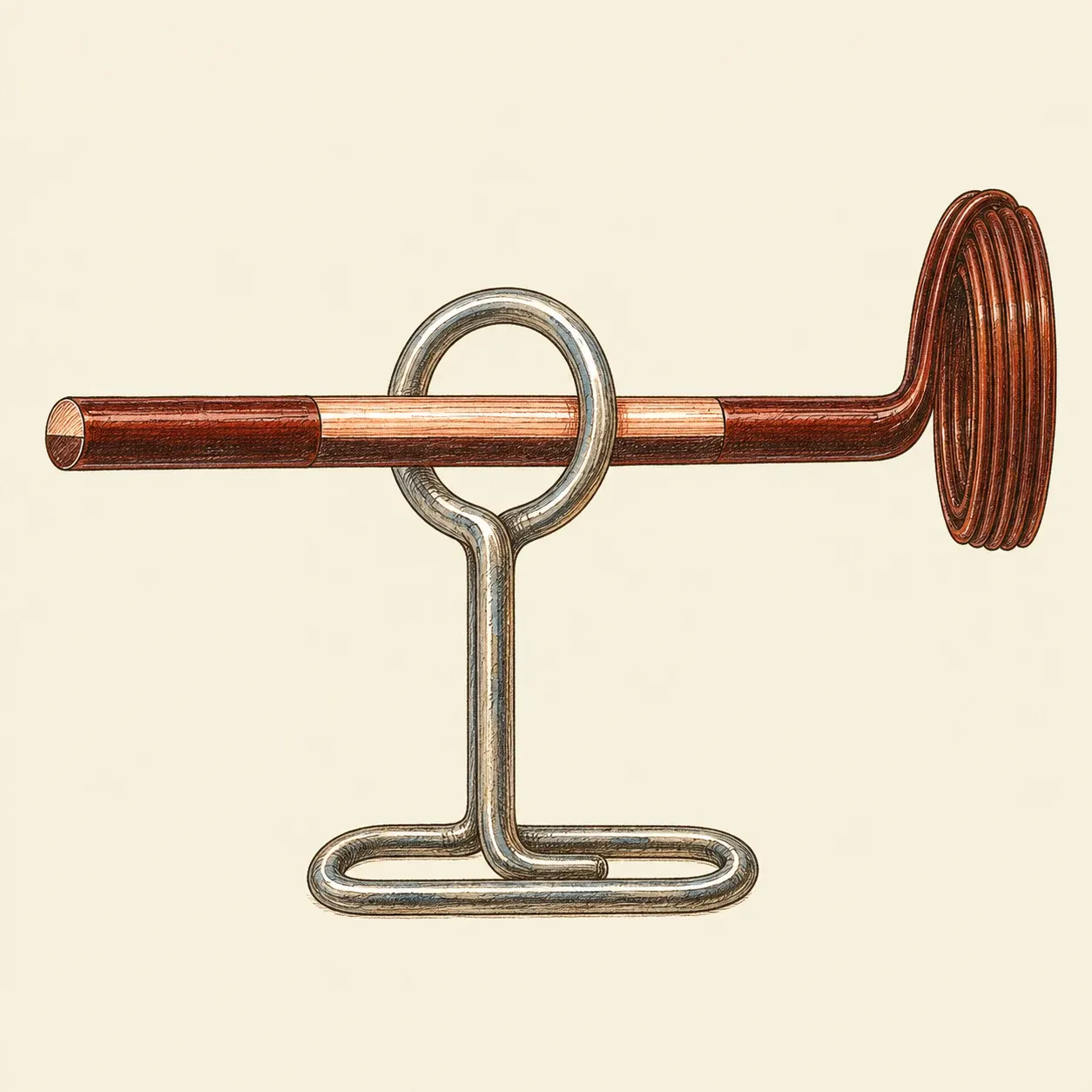 The paper-clip commutator: bare copper on top, enamel left underneath, so current flows only during the half turn when the bare side rests on the clip.
Make the commutator. On one end, sand off all the enamel. On the other, hold the coil upright as it will stand and remove the enamel from the top half of the wire only. That end conducts for half a turn and is insulated for the other half, so the coil is never pushed backwards; it coasts through the dead half on its momentum.
Mount the supports. Bend each paper clip into an upright with a flat foot at the bottom and a small loop at the top. Stretch the rubber band lengthwise round the cell, over both feet, so that it presses each clip firmly against one terminal. Set the magnet on the side of the cell under the loops, where it clings to the steel casing. Lay the coil in the loops a few millimetres above the magnet.
Start it. Give the coil a light flick. If it only rocks, turn it end for end or sand the bare side again.
Scale up. A stronger magnet gives more torque; more turns help too, as long as the longer wire does not cut the current too much. A workshop motor uses several coils on a laminated iron core, with a commutator of many segments and spring brushes, as on the plate.
Safety. Use one or two ordinary 1.5 V cells and nothing else: never the mains, a car battery or a lithium-ion pack. The coil is close to a short circuit, and those sources can push enough current to burn skin, melt the wire or start a fire. Even a small cell heats up, running or not: keep each run short and supervised, and disconnect the cell when it or the wire feels warm, before adjusting or sanding, and after use. Neodymium magnets snap together hard enough to pinch skin and can shatter. Keep them away from pacemakers and other medical implants, and out of reach of small children: two swallowed magnets can pull together through the wall of the gut.
History and evolution
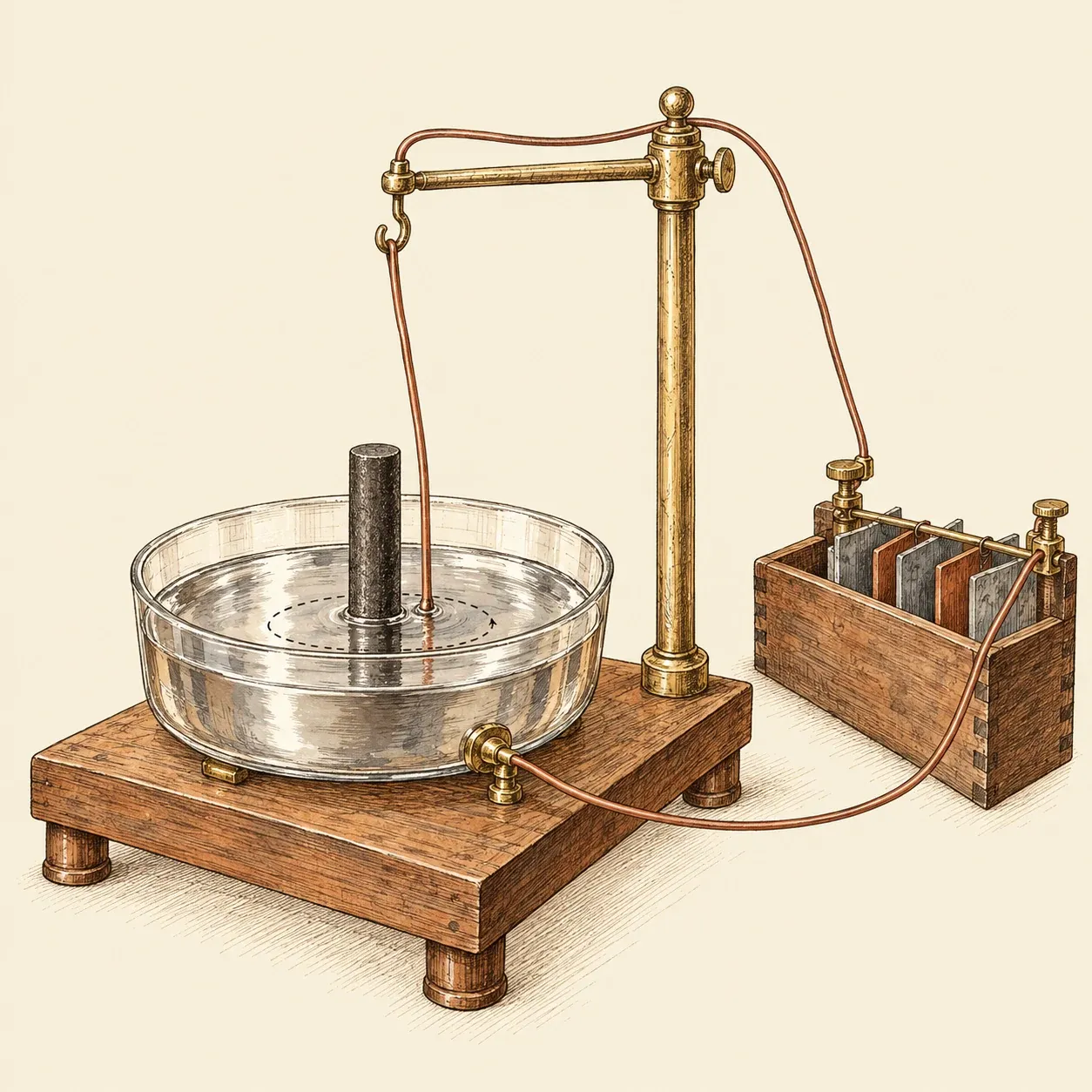 Faraday’s rotation (1821): the free end of the wire circles the magnet.
In 1820 Hans Christian Ørsted saw a compass needle swing beside a wire carrying current. On 3 September 1821 Michael Faraday made a wire dipping into mercury circle a magnet, and in 1822 Peter Barlow spun a star-shaped wheel between magnet poles. Both were demonstrations with little usable power. Strong fields came with the electromagnet, which William Sturgeon made in the mid-1820s, and around 1832 William Ritchie and Sturgeon built rotating machines with a commutator.
In May 1834, in Königsberg, Moritz Hermann Jacobi finished a motor with eight horseshoe electromagnets that developed about 15 watts. This plate takes 1834 as its date: Faraday showed the principle and Sturgeon’s small engine already turned a roasting spit, but Jacobi’s machine was far more powerful, and no other builder matched it before about 1839. Thomas Davenport’s American patent came in 1837.
Batteries made these motors costly to run until the generator brought cheap current. In 1873 a Gramme dynamo was found to run as a motor when fed by another one. Galileo Ferraris in Turin worked out the rotating field from 1885 and published in March 1888; Nikola Tesla, working separately in New York, was granted his induction-motor patent on 1 May 1888. Today permanent-magnet motors switched by electronics drive drones and electric cars.