Gear pump
Liquid carried between meshing teeth
Contents
- 1Crank on the driving shaft
- 2Driving gear
- 3Driven gear
- 4Casing around the teeth
- 5Suction pipe
- 6Rising pipe
A gear pump moves a liquid with two toothed wheels that mesh inside a close-fitting casing. Where the teeth come apart, liquid flows into the spaces between them; it is carried round the outside of each wheel and pushed out where the teeth mesh again. Johannes Kepler devised a valveless gear pump for draining mines: in 1602 he ordered a brass model from two Augsburg craftsmen, who never delivered it, and Jost Bürgi made one in 1604; a book printed in Lyon in 1719 describes one sunk in a well and turned from a hand wheel to raise water. Gear pumps now circulate engine oil, feed fuel and drive the hydraulics of tractors and building machines.
What it is
A gear pump is a pump with no valves and no piston. Two toothed wheels of the same size mesh with each other inside a casing that hugs the tips of their teeth and their flat faces. One wheel is fixed on a shaft that comes out through the casing and is turned by a crank, a motor or an engine, and it drives the other. A pipe enters the casing on one side of the place where the teeth meet, and another leaves it on the other side.
The pump is a positive displacement pump: at each turn it delivers about the same volume of liquid, the volume of the spaces between the teeth, so its flow follows the speed of the shaft. It works best with liquids that are thick enough to fill the small gaps between the moving parts, such as oil. It also lifts water, as the pump described in 1719 did, and it can draw a liquid up a suction pipe as well as push it up a rising pipe.
How it works
Seen from the front, with the inlet below the meshing point and the outlet above it, the left gear turns clockwise and the right gear anticlockwise. In the middle, the teeth of both gears move downwards together. At the bottom they come out of mesh: each tooth leaves the gap it was filling in the other gear, the space there grows, and liquid from the inlet flows in to fill it.
Each gap between two teeth is then closed off by the wall of the casing and carries its small load of liquid upwards round the outside of its gear, the left gear along the left wall and the right gear along the right wall. At the top the teeth mesh again. Each tooth enters a gap of the other gear and pushes the liquid out of it, and the liquid has nowhere to go but the outlet. It cannot slip back through the middle, because the teeth in mesh close the way. Turning the shaft the other way makes the pump work backwards, with the outlet as the inlet.
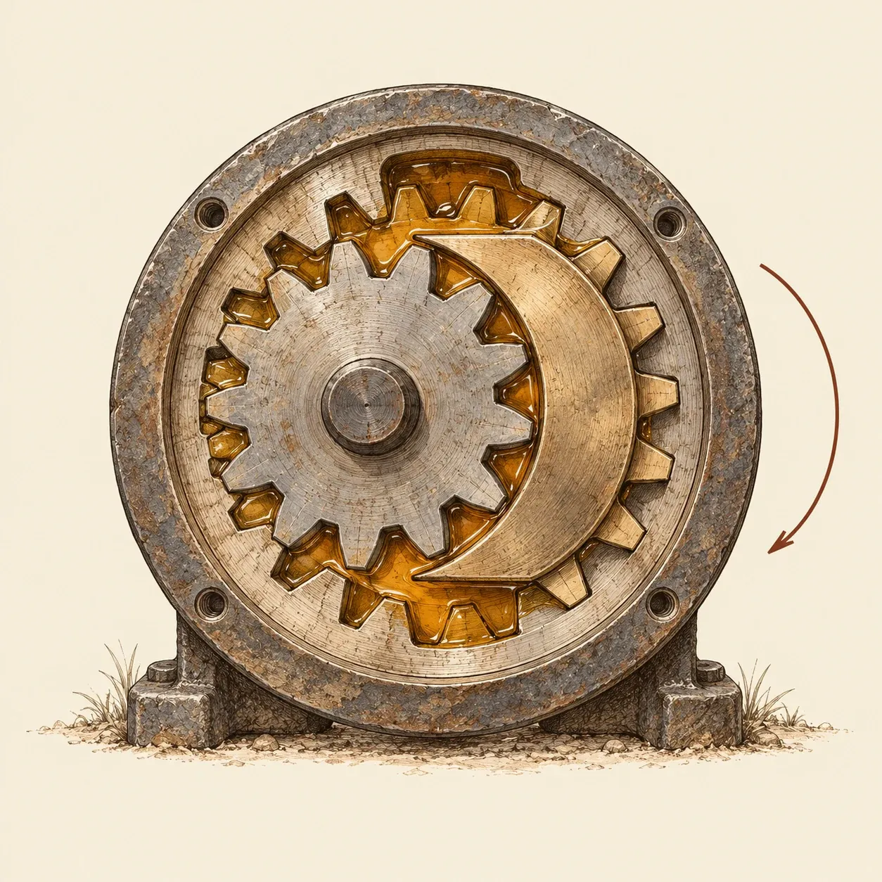 An internal gear pump: a small gear turns a ring with inner teeth, and a fixed crescent closes the space between them.
The pump leaks a little inside, through the narrow gaps between the tooth tips and the casing and across the faces of the gears. The leak grows with the outlet pressure and with thinner liquids, which is why gear pumps are made to close tolerances and do well with oil. Where the shaft comes out of the casing, a packed gland or a seal stops the liquid from escaping. Because each turn pushes out a fixed volume, a gear pump with a blocked outlet keeps raising the pressure until a pipe or a part gives way, so hydraulic circuits fitted with one also carry a relief valve that opens and sends the liquid back to the tank. A second kind, the internal gear pump, puts a small gear inside a ring with teeth on its inner side. The two are off-centre, so their teeth mesh on one side and are far apart on the other, where a fixed crescent fills the space between them. Liquid is carried in the gaps along both faces of the crescent, the same way it is carried round the casing of the external pump.
How to do it
This clear model shows the liquid travelling round the gears. You need two identical plastic spur gears from a model shop, about 4 cm across and with a hole for a 4 mm axle, a piece of plywood or acrylic exactly as thick as the gears, two pieces of clear 3 mm acrylic of the same size, a Forstner bit about 1 mm larger than the outer diameter of the gears, a drill on a stand, 4 mm steel rod, epoxy glue, eight small bolts with nuts, 6 mm clear plastic tubing, petroleum jelly, a strip of wood for a crank, two cups and some water coloured with food colouring.
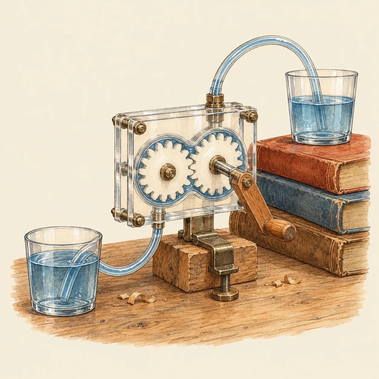 The crank turns the gears, and coloured water climbs from the lower cup into the upper one.
Put the two gears on the table with their teeth in mesh and measure the distance between the centres of their holes. Mark two points that far apart on the middle piece and drill a hole with the Forstner bit at each, so that the two holes overlap in a figure-eight. The gears should turn inside it without touching the wall. Clamp the three pieces together and drill 4 mm holes through all of them at the two centres. In the back piece, drill a hole just below the middle of the figure-eight and another just above it, and glue a short length of tube in each. Glue one gear to a long piece of rod and the other to a short one. Smear petroleum jelly on both faces of the middle piece, put the gears in place and bolt the three pieces together around the cavity, with the long rod passing out through the front. Glue the crank to the end of the long rod.
Fill the cavity with water through the upper tube, put the lower tube in the coloured water and lead the upper tube to the second cup, higher up. Turn the crank so that the teeth in the middle move downwards. After a few turns the coloured water rises in the tube, and you can watch it travelling round the outside of each gear. Turn the crank the other way and the water runs back.
Safety. Clamp the acrylic firmly to the drill stand and wear safety glasses: a Forstner bit can catch the sheet and spin it round, or crack it and throw sharp chips.
History and evolution
Johannes Kepler wrote that he had been working since 1597 on a pump without valves, which would work by turning in a circle instead of stopping and starting like an ordinary pump. On 24 October 1602, in Prague, he signed an agreement with Hans and Balthasar Miller, two brothers from Augsburg, who were to finish a brass model of it within about two months; Kepler paid them 27 florins in advance, and the model was never delivered. In a letter dated 22 December 1604 he recalled a first model made in wood and reported that the instrument maker Jost Bürgi had now built a version in brass. Fritz Staudacher, a historian of Bürgi, also dates Bürgi’s metal prototype to 1604 and describes the machine as a gear pump for pumping water out of mine galleries. The German Patent and Trade Mark Office likewise credits Kepler with a gear pump without valves, devised for a mine owner who needed to pump water out of his mine. A gear pump also appears in a book printed in Lyon in 1719, in which Gaspard Grollier de Servière described the cabinet of machines and models left by his grandfather Nicolas. Among the machines for raising water is one presented as very simple, for lifting water from a well or a reservoir to a considerable height. Two solid pinions, of wood or metal, fill an oval box in which they turn freely and mesh with each other. The box is sunk in the water and closed everywhere except at the bottom, where the water enters, and at the top, where a pipe rises from it.
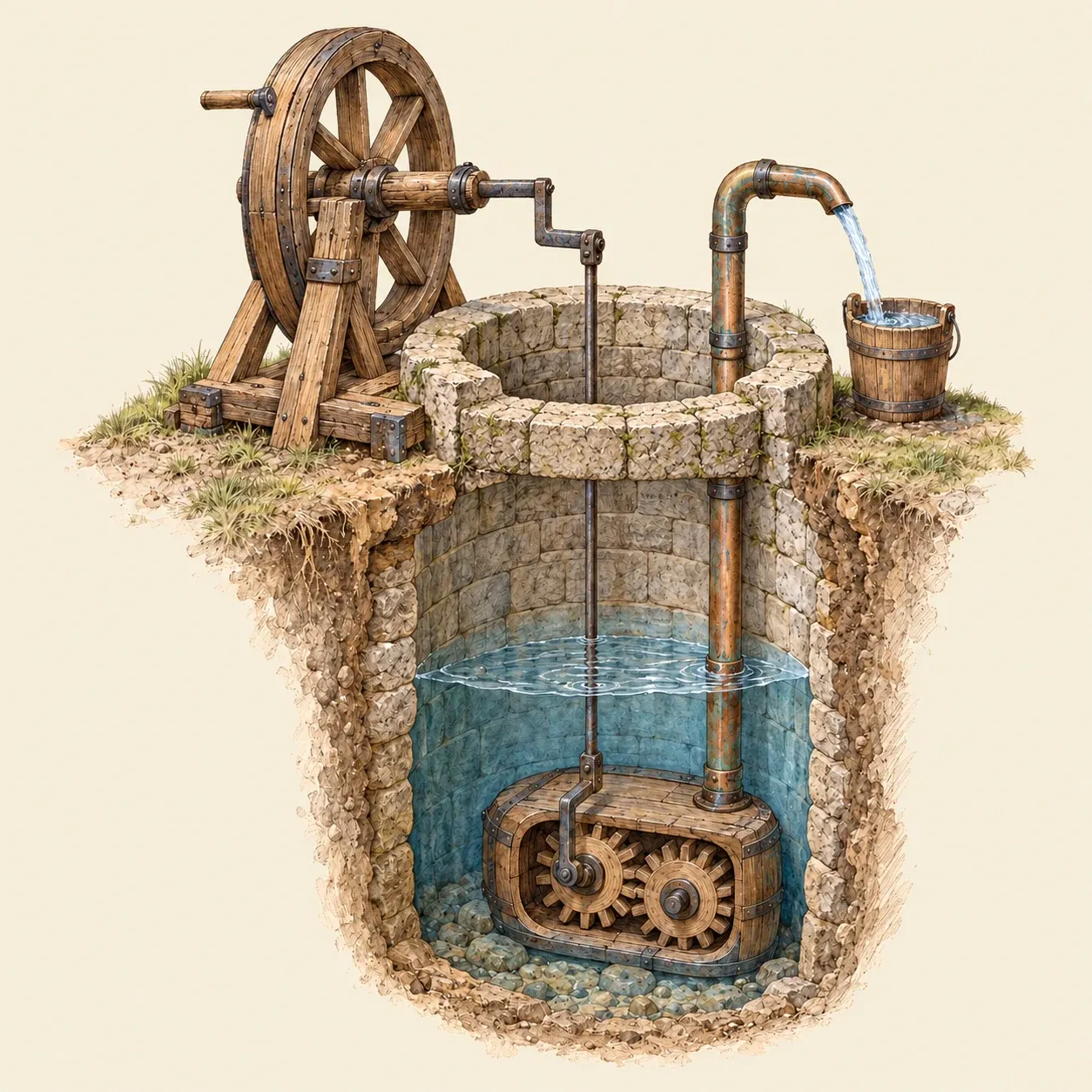 The Servière machine: two pinions in an oval box under water, turned from a hand wheel above the well, push the water up a pipe.
A man turned a large wheel with a handle, and cranked axles linked by an iron piece turned one of the pinions. The text explains that the water caught between the teeth at the bottom of the box is carried up to the top, where the water that keeps arriving presses it into the pipe, and it cannot return the way it came. Thomas Ewbank reproduced the figure in a history of machines for raising water published in New York in 1850. He added a suction pipe, described the shaft leaving the case through a stuffing box or a leather collar, counted the pump among the oldest and best of rotary pumps, and noted that it was thought to be older than the collection that preserved it. He also recorded that the faces of the teeth were sometimes grooved to hold strips of leather that sealed the gaps, and that the rotary steam engine of William Murdoch copied the same arrangement.
To work against high pressure, a gear pump needs metal gears and bores made to small clearances. Gear pumps are compact, have few parts and tolerate thick liquids, and they now serve as oil and fuel pumps in engines and as the hydraulic pumps of tractors and building machines, where they feed the cylinders of a hydraulic arm. It uses the same meshing gears as clocks and mills to do the work of a piston pump, without valves.