Hydraulic manipulator arm
Joints moved by oil under pressure
Contents
- 1Slewing column
- 2Inner boom and its lifting cylinder
- 3Outer boom and its folding cylinder
- 4Grab
- 5Control valves with their levers
- 6Piston and rod inside a cylinder
A hydraulic manipulator arm is a chain of rigid booms joined by pins, in which each joint is moved by its own hydraulic cylinder. A pump sends oil under pressure, and an operator, or later a controller, opens valves that send it to one side or the other of each piston. Small cylinders can thus lift heavy loads and place them precisely. In 1947 Vaino Holopainen and Roy Handy built a hydraulic backhoe in the United States; their firm, Wain-Roy, filed a patent in 1948 for a tractor backhoe whose boom, dipper stick and stabiliser each had their own cylinders. The arms of loader cranes, excavators and early industrial robots work on the same principle.
What it is
A hydraulic manipulator arm moves loads with a chain of rigid members joined end to end by pins, like the bones of an arm. Each joint is worked by a hydraulic cylinder fixed across it, from one member to the next: when the cylinder grows longer or shorter, the joint opens or closes. The arm sits on a base that turns, and at its end it carries a hook, a grab, a bucket or a gripping hand. A pump, driven by an engine or an electric motor, supplies the oil, and a set of valves decides which cylinder moves, in which direction and how fast.
The best known examples are the loader crane mounted behind the cab of a lorry, whose folding boom lifts pallets, timber or building materials onto the platform and stows itself when the lorry drives off, the backhoe on the back of a tractor and the arm of the hydraulic excavator. American safety rules define the articulating crane as one whose boom is made of folding, pin-connected members, usually moved by hydraulic cylinders. The same principle moved the arms of early industrial robots.
How it works
A hydraulic cylinder is a tube closed at both ends, with a piston that slides inside it and a rod that leaves through one end, through a seal. Oil sent into the closed end pushes the piston and the rod out; oil sent into the rod end pulls it back in. The push equals the oil pressure multiplied by the area of the piston, so a cylinder of modest size, fed with oil at a pressure of a few hundred times that of the atmosphere, pushes many tonnes. On the rod side the rod takes up part of the area, so the cylinder pulls back with less force than it pushes.
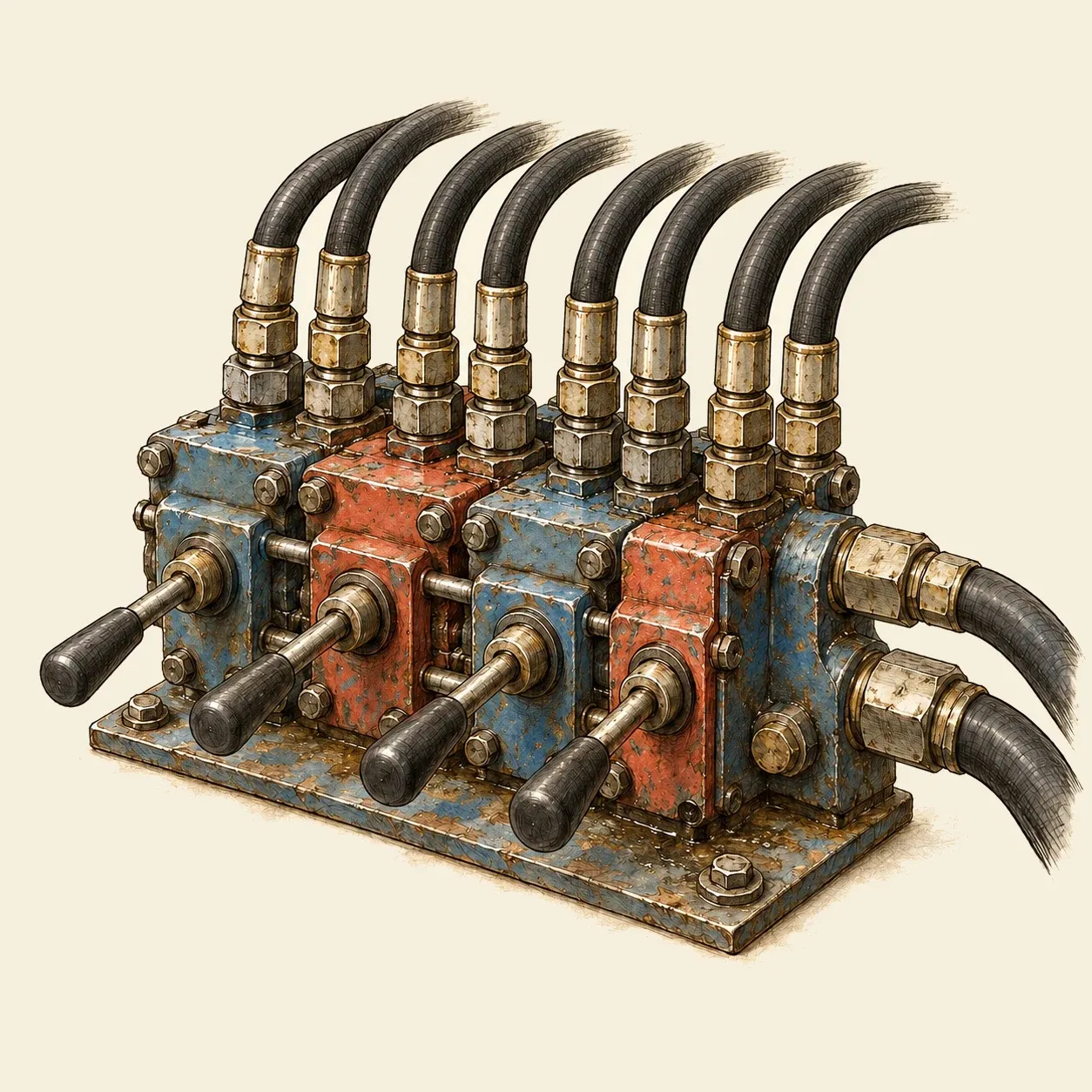 A bank of control valves: each lever sends oil to one cylinder, one way or the other.
Each cylinder has its own valve in a bank. Inside each valve a sliding spool, moved by a lever, connects the pump to one end of the cylinder and the other end to the return line to the tank, or the reverse, or closes both ends so that the cylinder holds its position. Pushing a lever further opens the passages wider and moves the joint faster. A relief valve at the pump limits the pressure the pump can build, for instance when a cylinder reaches the end of its stroke. It cannot protect a cylinder whose ports are closed, because a load pressing on that cylinder raises the pressure of the oil trapped inside it. A cylinder that holds a load therefore has its own valve, such as a counterbalance valve fitted close to it. This valve locks the oil in without leaking, keeps the load from falling if a hose fails and lets it down only when the operator sends oil to lower it. With a spool that closes both ends, a shock or an outside force that raises the pressure too far is released by a separate relief valve on each line to the cylinder. The counterbalance valve can release such a surge itself only when the spool, in its middle position, joins both lines to the tank.
The arm trades force for movement. A cylinder fixed close to the pin of a joint moves only a short way, but the end of the boom swings through a wide arc, as the forearm swings when a muscle near the elbow contracts. For the same reason the cylinder must push much harder than the weight held at the end of the boom, just as the muscle pulls far harder than the weight in the hand. The designer chooses where each cylinder is fixed to trade force against reach and speed. Some cylinders only push and let the weight of the boom bring them back: the Wain-Roy patent of 1948 used a single-acting cylinder to raise its boom and double-acting ones to work its digging arm and its stabiliser.
How to do it
This model arm is moved by water in plastic syringes, which act as small hydraulic cylinders. You need stiff corrugated cardboard or 3 mm plywood, a small wooden board for the base, a wooden block for the column, two short bolts with nuts and washers for the joints, four plastic syringes of the same size without needles, two lengths of tubing about 50 cm long that fit the syringes tightly, cable ties, a length of 6 mm dowel, water, a hot glue gun, a craft knife, a cutting mat, a drill and a paper clip for the hook.
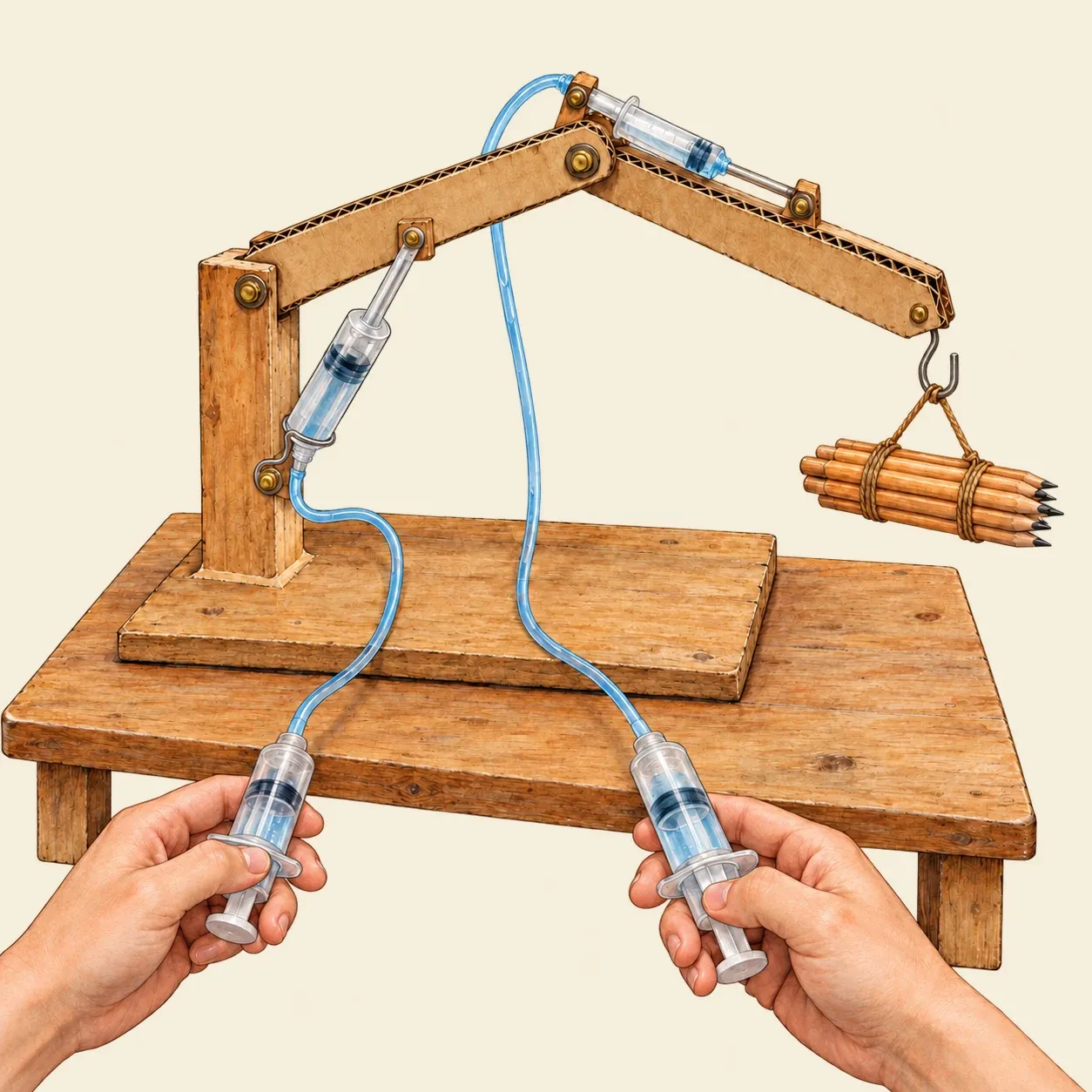 Each hand syringe drives one joint: pressing it pushes the syringe on the arm out, and pulling it draws it back in.
Cut two arms from the cardboard or plywood, each two layers thick and about 20 cm long, and drill a hole near each end. Glue the column upright on the base and bolt the inner arm to its top, so that it can swing up and down, then bolt the outer arm to the end of the inner arm. Fill a syringe with water, connect it with a tube to an empty syringe whose plunger is pushed in, and push out any air. Do the same with the other pair. Each arm syringe must be free to turn at both ends, because the points it joins move along arcs. With a cable tie, strap a 4 cm piece of dowel across the barrel near its finger grip, parallel to the joint bolts, and glue another piece across the thumb pad of the plunger. For each piece of dowel, glue two small cardboard cheeks to the model, a little less than a dowel’s length apart, each with a hole in which the dowel end turns freely. Put the cheeks for the first syringe low on the column and under the inner arm, a short way from the joint, so that pushing the plunger out lifts the arm. Put those for the second syringe on the inner arm and on the outer arm just past the joint, so that it unfolds the outer arm. Spring the cheeks apart to set the dowel ends in their holes. Bend the paper clip into a hook and glue it to the end of the outer arm.
Hold one hand syringe in each hand. Press the first and the inner arm rises; pull it back and the arm comes down. Press the second and the outer arm unfolds. Try to pick up a small load with the hook and set it down elsewhere. Each push on a hand syringe moves the plunger on the arm by the same distance, and because that plunger is fixed close to the pin, the end of the arm moves much further.
Safety. The nozzle of the hot glue gun and fresh glue can burn: keep your fingers away from them and let each joint cool before you handle it.
History and evolution
Eric Sundin made skis in Hudiksvall, in Sweden. His growing knowledge of hydraulics led him to found Hydrauliska Industriaktiebolaget, known as HIAB, in 1944, and in 1947 the firm launched a mobile hydraulic crane built in series, the HIAB 190.
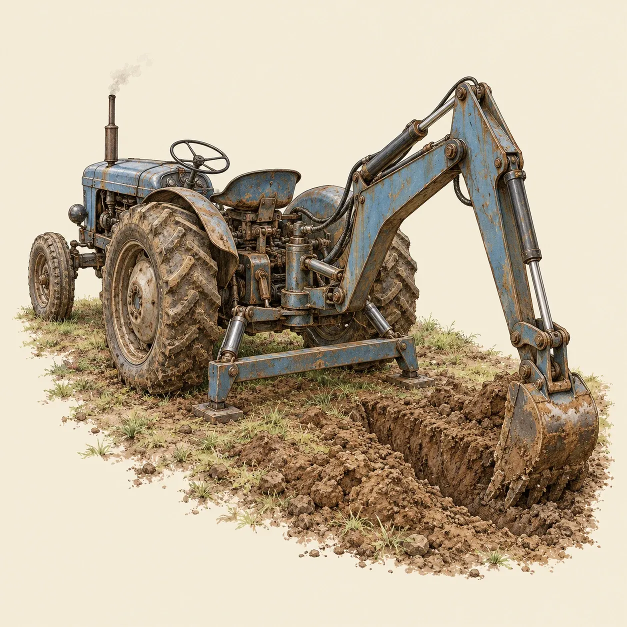 A tractor backhoe: separate cylinders raise the boom, work the digging arm and press a stabiliser into the ground.
In the United States, Vaino Holopainen and Roy Handy built a hydraulic backhoe in 1947, which became the founding product of their firm, the Wain-Roy Corporation. Holopainen filed a patent in July 1948 for a power-operated shovel mounted on the back of a tractor. Its swing frame pivoted on vertical pins at the rear of the tractor and carried a boom, a dipper stick and a bucket. A double-acting cylinder swung the dipper stick to dig and dump, a single-acting cylinder raised the boom, two cylinders swung the whole arm from side to side, and two more lowered a cross bar into the ground behind the tractor to anchor it. One control handle worked the boom and the stabiliser through a three-way valve, so that the boom could only be used once the stabiliser was set.
George Devol filed a patent in 1954 for a programmed machine that moved articles with an arm driven by hydraulic actuators, following positions recorded in a memory. The Unimate robot that came from it began work at General Motors in 1961, lifting hot pieces of die-cast metal. Industrial robots later moved to electric motors, while hydraulic arms still serve where the loads are heavy, on loader cranes and excavators. They work by the principle of the hydraulic press, applied at each joint, and the crane mounted on a lorry takes its oil from a pump driven by the lorry’s engine.