Self-climbing tower crane
A crane that adds sections to its own mast
Contents
- 1Jib and counter-jib
- 2Climbing frame
- 3Hydraulic cylinder
- 4New mast section on its carriage
- 5Lattice mast sections
- 6Tie to the building
A self-climbing tower crane makes its own mast taller. A frame around the top of the mast carries the jib and its machinery; a hydraulic cylinder pushes this frame and everything above it up by the height of one section, and a new section is rolled in through an opening in its side. The crane can thus keep its hook above a building that rises floor by floor. Such cranes appeared in the mid-1950s, in France and in Germany. According to its own history, the French maker Potain built a crane with a climbing cage of this kind, raised at first with cables; hydraulic cylinders later replaced the cables. In the same period, Liebherr designed its self-climbing 25H in Germany.
What it is
A tower crane stands on a vertical mast built from identical lattice sections of steel, joined end to end with pins or bolts. On top of the mast sits the slewing part, which turns as a whole: a long horizontal jib along which a trolley carries the hook, a short counter-jib loaded with concrete blocks to balance it, the winches and the operator’s cab. The crane is put up at the start of a building job, often with the help of a mobile crane, to a first height.
A self-climbing crane can then grow without another crane. It adds sections to its own mast, so that its hook stays above the building as the floors go up, and it removes them the same way when the job is done. Many climbing cranes do this outside the building, on their own mast, which is tied to the building at intervals to keep it steady. Others stand inside the building and climb the structure itself as it rises.
How it works
For climbing on its own mast, the crane carries a climbing frame, a steel cage that surrounds the top of the mast just under the slewing part and is fixed to it. Rollers or guides on the inside of the frame run along the corner posts of the mast. One face of the frame is open, and in front of that opening a short rail sticks out with a carriage hanging from it. A hydraulic cylinder fixed to the frame pushes down on a cross bar that rests on lugs of the mast, and a small electric pump unit feeds the cylinder with oil under pressure.
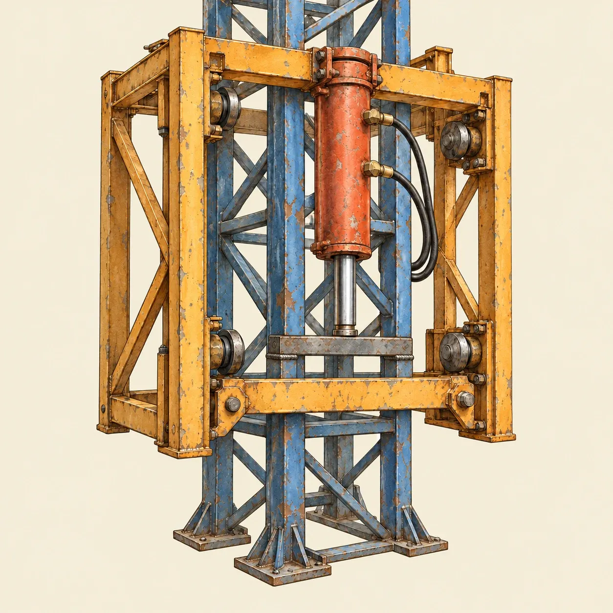 The foot of the cylinder: a cross bar rests on two lugs of the mast, and the cylinder pushes the frame upwards from there.
To climb, the crane first lifts a new section with its own hook and hangs it on the carriage. The trolley is moved along the jib to the radius given by the maker, sometimes with a load on the hook, so that the centre of gravity of everything the frame will carry lies over the climbing cylinder. The cylinder can then lift that weight without tipping the frame against its guides. The cylinder is pressurised to take the weight, and the joint between the top section and the slewing part is undone. The cylinder pushes, and the frame, the slewing part, the jib and the counter-jib rise together along the mast, until the gap opened inside the frame is as tall as one section. The carriage rolls the new section in through the opening, onto the top of the mast, where it is pinned or bolted to the section below. The cylinder lowers the top onto it, the upper joint is closed, and the crane is one section taller.
The steps are repeated section after section. After climbing, the frame is lowered to the next tie or to the foot of the mast, or taken off. A free-standing mast can only be so tall, so a mast that rises along a building is tied to it with steel braces fixed to its floors or walls. An inside-climbing crane works differently: its short mast stands on frames wedged in openings of the floors, and the cylinder lifts the whole crane from one set of floor frames to the next one higher up, so that the building carries the crane.
How to do it
This tabletop model shows a climbing frame lifting itself up a mast with a water jack. You need six to eight identical wooden blocks of square section, for instance cut from 4 cm square timber, each a little shorter than the travel of the syringes used, a length of 6 mm dowel, a flat board for the base, card or 3 mm plywood for the frame, a wooden ruler for the jib, two plastic syringes of the same size, about 40 cm of tubing that fits them tightly, water, a wooden coffee stirrer, adhesive tape, a small rubber band, a drawing pin, a hot glue gun, a craft knife, a cutting mat and a steel rule.
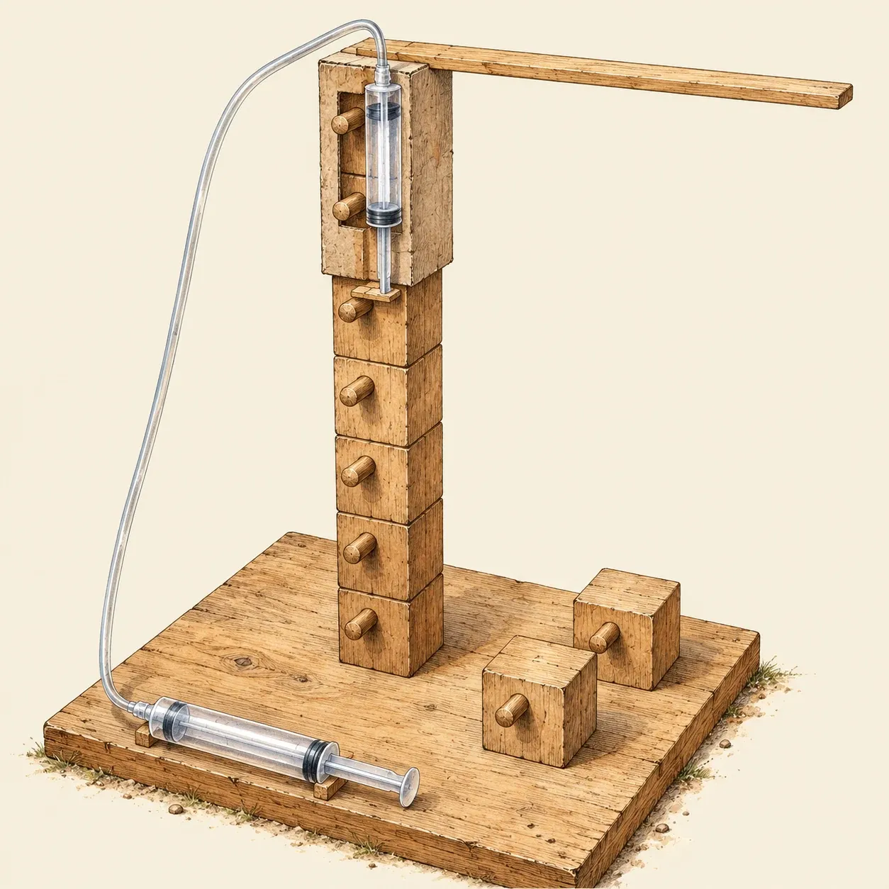 Pressing the hand syringe pushes the plunger of the other one down onto a peg of the mast, and the sleeve rises.
Glue a 2 cm piece of dowel to the middle of one face of each block, near its top, so that it sticks out like a step. Glue the first block upright on the base and stand the others on it, pegs on the same side. Make the frame as a square sleeve with a lid, a little more than two blocks tall, that slides on the blocks without much play. In the face on the peg side, cut a slot along its whole height, a little wider than the pegs, so that they can pass. In the opposite face, just under the lid, cut a window as tall as one block. Glue the ruler to the lid as the jib. Fill one syringe and the tube with water without air bubbles and connect the second syringe with its plunger pushed in. Glue that second syringe upright on the outside of the sleeve, beside the slot, plunger downwards. Glue a small wooden stop across the end of the plunger. Cut a foot about 3 cm long from the coffee stirrer and hinge it under the stop with a strip of tape, so that it reaches over the slot. Press the drawing pin into the top of the stop and stretch the rubber band from the pin to the tip of the foot: the band holds the foot up against the stop, so the foot can fold downwards but not upwards. Set the sleeve on the mast, lid on the top block, with the foot resting on the peg of the block just below the window.
Slowly press the hand syringe. The plunger on the sleeve moves out, the foot, held flat by the stop, pushes on the peg, and the sleeve with its jib rises until the window is clear above the top block. Push a new block in through the window, peg first, so that the peg enters the slot, and slowly draw back the hand syringe. The sleeve settles on the new block and the plunger rises. When the foot meets the peg of the next block from below, it folds down, slips past it, and the rubber band pulls it back flat above the peg. Each cycle adds one block, which is how the real crane grows by one section.
Safety. The nozzle of the hot glue gun and fresh glue can burn: keep your fingers away from them and let each joint cool before you handle it.
History and evolution
Tower cranes with a horizontal jib, along which a trolley carries the load to the exact place it is needed, became common on European building sites in the rebuilding after the Second World War. Makers such as Liebherr in Germany and Potain in France built them to be carried to the site and put up quickly, and some already had telescopic masts, but the height of these masts was limited by the length of their own pieces.
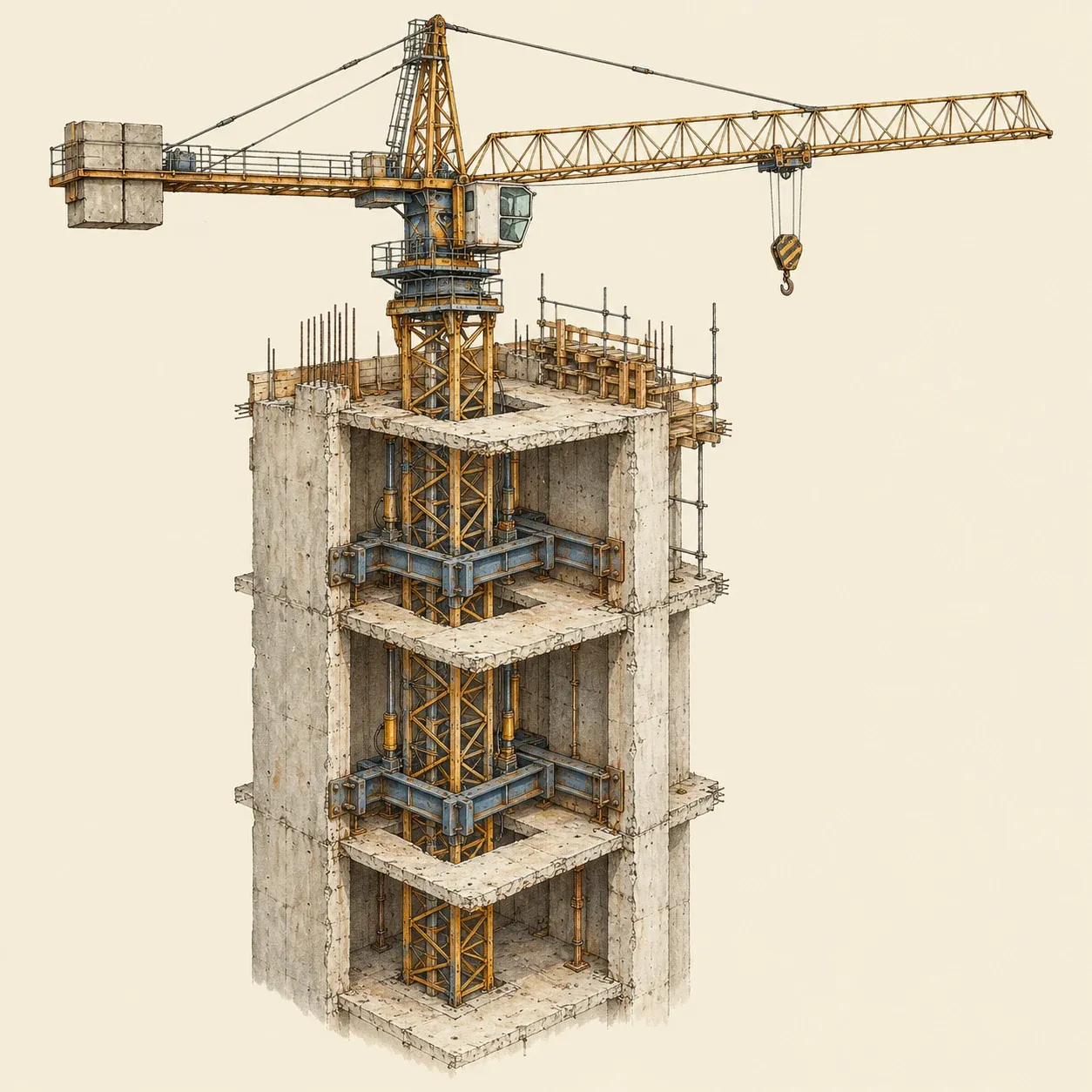 An inside-climbing crane stands inside the building and is lifted from floor to floor as the structure rises.
Climbing cranes appeared in the mid-1950s. According to the company’s own history, a Potain engineer named Janier imagined a cage that slid around the mast and allowed mast sections to be added to raise the crane. The cage was at first raised with cables; the same history says that hydraulic cylinders later replaced them for raising the mast, which made erection quicker and safer. In Germany, Liebherr designed a self-climbing tower crane, the 25H, in the same years. Engineering News-Record notes that such cranes soon became an important tool for tall structures. Climbing frames driven by a hydraulic cylinder and a pump unit powered by an electric motor have remained the usual method since then. Makers now sell them for cranes that climb outside a building and for cranes that climb inside it, carried by its floors. In the United States, federal rules ask that before any climbing, top or inside, an engineer check that the building can bear the forces brought by the braces or by the crane itself. The crane itself still lifts with a hook, a winch and pulley blocks, and its mast and jib are lattices of steel.