Sheet-metal shear
A straight blade sliding past a fixed one
Contents
- 1Shaft with eccentrics
- 2Connecting link
- 3Upper blade on its sliding beam
- 4Fixed lower blade
- 5Guide in the end frame
A sheet-metal shear cuts sheet and plate between two hardened steel blades that slide past each other with a very small gap. In the guillotine shear a long straight blade, set at a slight slant, moves down in guides past a fixed one and cuts across the whole width of a sheet. Metalworkers' shears are listed among the tools of a workshop in the early 12th century, and steam-driven shearing machines were built in British engineering works in the first half of the 19th century. On 31 January 1843 George Thorneycroft of Wolverhampton was granted a patent for a shear for wide plates of sheet iron, whose slanted upper blade, driven by eccentrics, moved in straight guides.
What it is
A sheet-metal shear cuts metal sheet or plate along a straight line between two blades. The blades pass each other face to face with only a very small gap between them, as the two blades of a pair of scissors do, and they do not meet edge to edge like a chisel on an anvil. Hand shears cut thin sheet with the force of one hand. Bench shears are fixed to a bench or a block and worked by a long lever. Shearing machines, driven by a crank turned by hand, by a steam engine or later by electric motors and hydraulic cylinders, cut plate of iron and steel.
The guillotine shear cuts the full width of a sheet at one stroke. A long lower blade is fixed horizontally along the edge of the bed. The upper blade is bolted to a heavy beam that slides up and down in guides in the two end frames, so that it can only move in a straight line past the lower blade. On the shear for wide plates of sheet iron that George Thorneycroft patented on 31 January 1843, as Charles Holtzapffel described it in 1846, a shaft above the beam carried three eccentrics, one at each end and one in the middle, and three links joined them to the beam. Each turn of the shaft pulled the beam down for one cut and lifted it again.
How it works
As the upper blade comes down, it presses the sheet against the edge of the lower blade. The metal first bends a little and rounds over along the top edge. The blades then push into it from both sides, and the metal is sheared, sliding along itself in a thin zone between the two edges. Before the blades have gone all the way through, cracks start at both edges and run into the metal, and when they meet, the strip falls away.
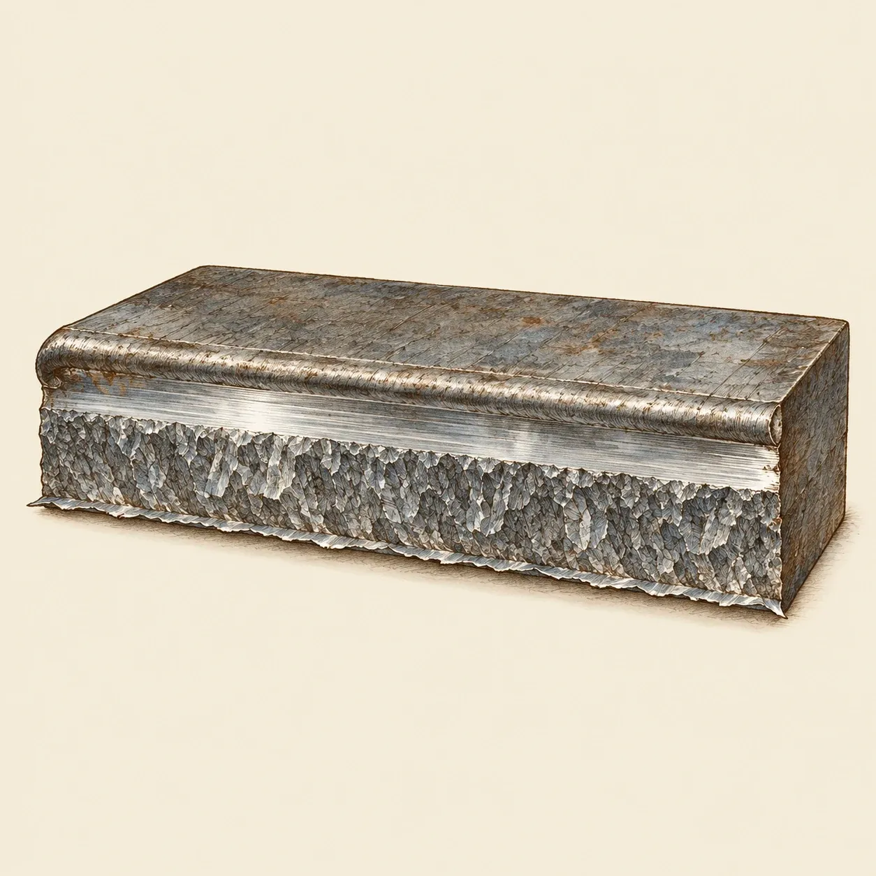 A sheared edge: the rounded corner, the smooth band rubbed by the blade, the torn band and the burr.
A sheared edge shows these stages one above the other. At the top is the rounded corner, below it a smooth, shiny band where the blade rubbed the metal, then a rough band where the metal tore, and at the bottom a small sharp burr. The gap between the blades, the clearance, decides the shape of this edge. It is a small fraction of the thickness of the sheet, larger for harder and thicker metal. Too large a gap rounds and distorts the edge and raises the burr; too small a gap makes the cracks miss each other and leaves a double cut.
The upper blade of a guillotine is set at a slight slant to the lower one, so that it enters the sheet at one end and the cut runs along the blade, as it does between the blades of scissors. Only a short length of metal is being cut at any moment, which needs much less force than cutting the whole length at once. A steeper slant needs less force, but the cut piece bends and twists more, so the slant is kept small. Because the beam moves in straight guides, the blades stay at the same small gap from one end of the cut to the other.
How to do it
This exercise cuts strips from soft aluminium sheet with hand snips and looks at the cut edge. You need a pair of straight-cut tin snips, a sheet of soft aluminium about 0.5 mm thick, sold for roofing flashing or model making, a steel rule, a marker, a fine flat file, a magnifying glass, an old pair of paper scissors with a screw at the pivot, a sheet of paper, cut-resistant gloves and safety glasses.
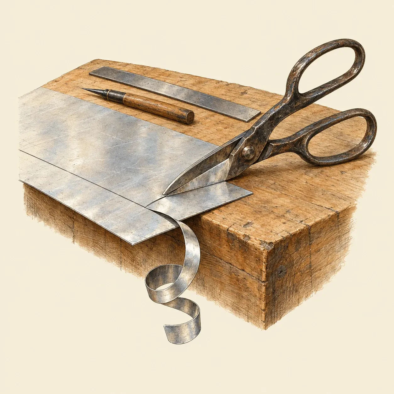 The snips cut along the line; the narrow strip curls away below the blades while the sheet stays flat.
Mark a line 2 cm from one edge of the aluminium with the rule and the marker. Put on the gloves and the glasses. Hold the sheet flat on the bench with the narrow strip hanging over the edge. Open the snips wide and set the line deep in the jaws, close to the pivot, where the force is greatest. Close the blades without letting the tips shut completely, open them, move forward and cut again, so that the cut runs on without small steps. The narrow strip curls down, the wide sheet stays flat. Look at the cut edge through the magnifying glass: you should see the rounded corner, a shiny band and a duller torn band, and feel a burr along one side. Remove the burr with a few strokes of the file along the edge.
To see what the gap does, loosen the screw of the old paper scissors by one turn and cut the paper. Where the blades spread apart, the paper folds between them instead of being cut. Tighten the screw again and the cut is clean.
Safety. Freshly cut aluminium edges and their burrs are as sharp as a knife: wear the gloves, file every edge you will handle and pick up the offcuts at once.
History and evolution
Shears made for cutting metal are rare among ancient finds. Flinders Petrie, surveying ancient tools in 1917, knew only one Roman pair of two-handed shears for metal, from Mainz, and an Anglo-Saxon one. In his treatise on the arts written in the early 12th century, the monk Theophilus lists the tools of a metalworker’s shop. Among the many pincers and tongs are cutting shears, large and small, made in two parts and fastened together by a rivet.
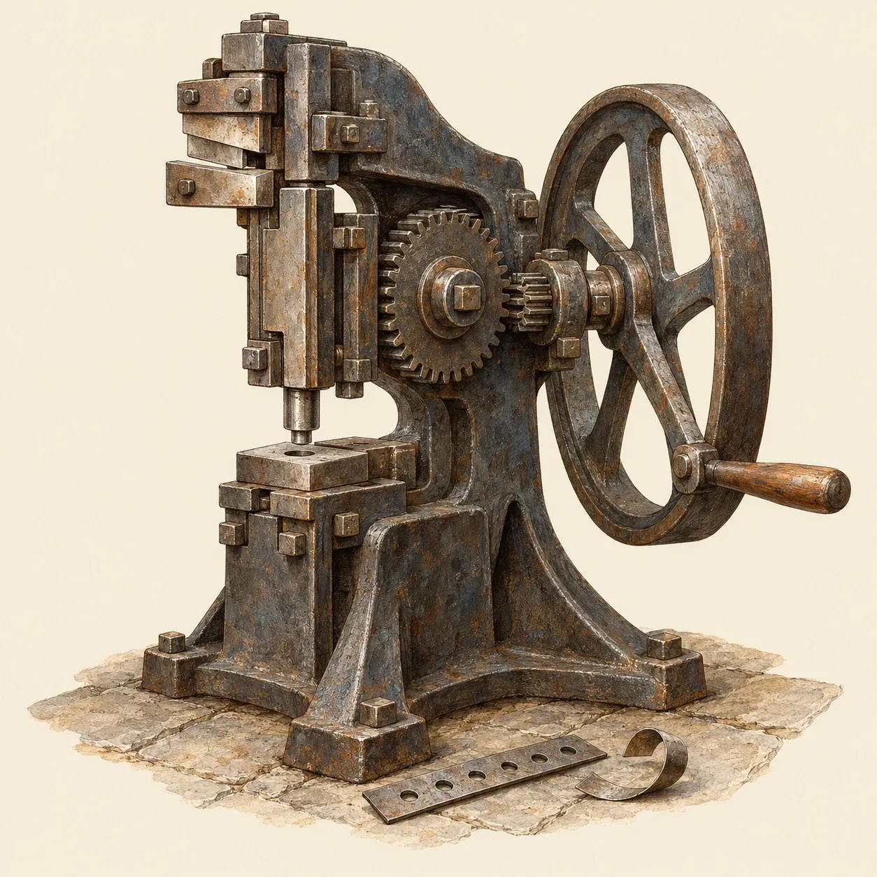 A punching and shearing machine: one slide, driven by an eccentric, punches holes below and shears plate above.
Machines took over in the engineering works of the early 19th century. Charles Holtzapffel, in his manual of 1846, wrote that the first shearing machines were little more than enlarged bench shears: a heavy lever on a pivot, with a blade near the pivot, raised and lowered by an eccentric or a cam turned by the steam engine. Richard Roberts of Manchester, who had learned his trade under Henry Maudslay in London, built such machines for boilermakers, who had to shear iron plates and punch rows of rivet holes in them. He changed the angle of the blades so that the plate no longer slipped out of them, then built a compact machine in which one slide, worked by an eccentric, carried a punch below and a shearing blade above. In this machine the blades approached in a straight line instead of along an arc. Holtzapffel noted that its blades were bevelled along their length so that they began to cut at one edge, which kept the work from sliding out and curled it very little. On 31 January 1843 George Thorneycroft of Wolverhampton patented a machine that extended this straight-line cut across the whole width of a sheet with a long upper blade moving in guides. A German technical journal printed its description the same year, and Holtzapffel described it in his manual. Guillotine shears for steel plate are now driven by electric motors or by hydraulic cylinders.