Resistor and rheostat
Opposing a current by a known amount
Contents
- 1Bare resistance wire wound in open turns
- 2Insulating tube
- 3Sliding contact on a brass bar
- 4Terminal
- 5Carbon composition rod
- 6Lead wire
A resistor is a part made to oppose an electric current by a known amount, turning some of the electrical energy into heat. A rheostat is a resistor whose value can be changed while current flows. Georg Ohm published the law that links current, voltage and resistance in 1827. In 1840 Moritz Jacobi and Charles Wheatstone showed instruments for adjusting the resistance of a circuit, and Wheatstone named his the rheostat in 1843.
What it is
A resistor lets an electric current through but opposes it by a set amount, measured in ohms. In a circuit it limits the current that a given voltage can drive, splits a voltage into smaller parts, or turns electrical energy into heat on purpose. Radios, chargers and computers contain dozens or thousands of them. The ENIAC computer, unveiled in 1946, had about 70,000.
A fixed resistor has a single value. In a variable resistor a contact slides along the resistive part, so the length in the circuit changes, and the resistance with it. With two terminals it is called a rheostat and adjusts a current, such as the speed of a motor or the brightness of a lamp. With three terminals, one at each end of the track and one on the slider, it is a potentiometer and takes off a chosen share of a voltage, as in the volume knob of a radio.
How it works
The current in a metal is a drift of electrons, and on their way they keep colliding with the atoms of the material and hand them energy, which warms the conductor. A wire of a given material resists more when it is longer and less when it is thicker. Copper conducts so well that the connecting wires of a circuit hardly count. Resistors use materials that conduct poorly on purpose, such as alloys of nickel, or carbon mixed with an insulating filler.
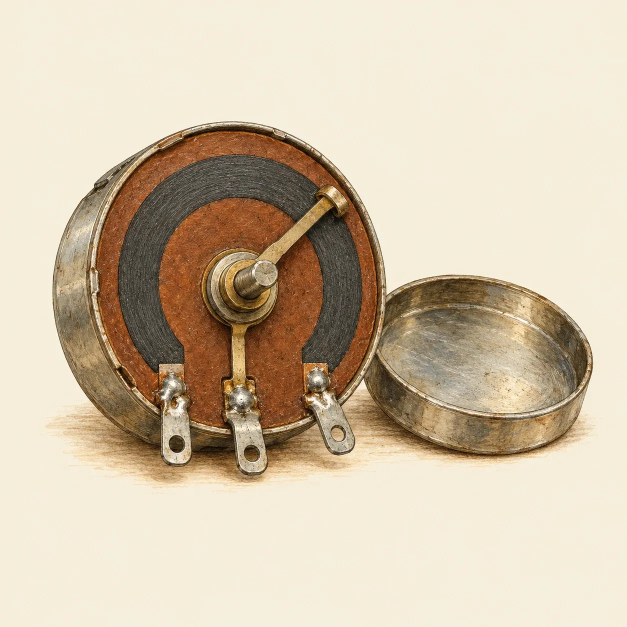 In a potentiometer, a wiper on the spindle slides along a carbon track between two end terminals.
Ohm’s law links the three quantities: the current in amperes equals the voltage in volts divided by the resistance in ohms. A resistor of 100 ohms across a 5-volt supply passes 0.05 amperes. The power turned into heat is the voltage multiplied by the current, here a quarter of a watt. Every resistor has a power rating, and one forced to shed more heat than it was built for runs hot, drifts in value and can burn. Large rheostats therefore carry bare wire in open turns on a ceramic or slate former, where the air cools it, while the small resistors of electronics are rated at a fraction of a watt.
Fixed resistors have been made in several ways. A wire-wound resistor carries a coil of alloy wire on an insulating core. The carbon composition resistor, the common type of the radio age, is a small rod moulded from carbon powder, a filler and a binder, with a lead wire set into each end; more filler gives a higher value. A film resistor has a thin layer of carbon or metal on a ceramic rod. The value is printed on the body or shown by coloured bands, a code that American radio makers drew up in the 1920s.
How to do it
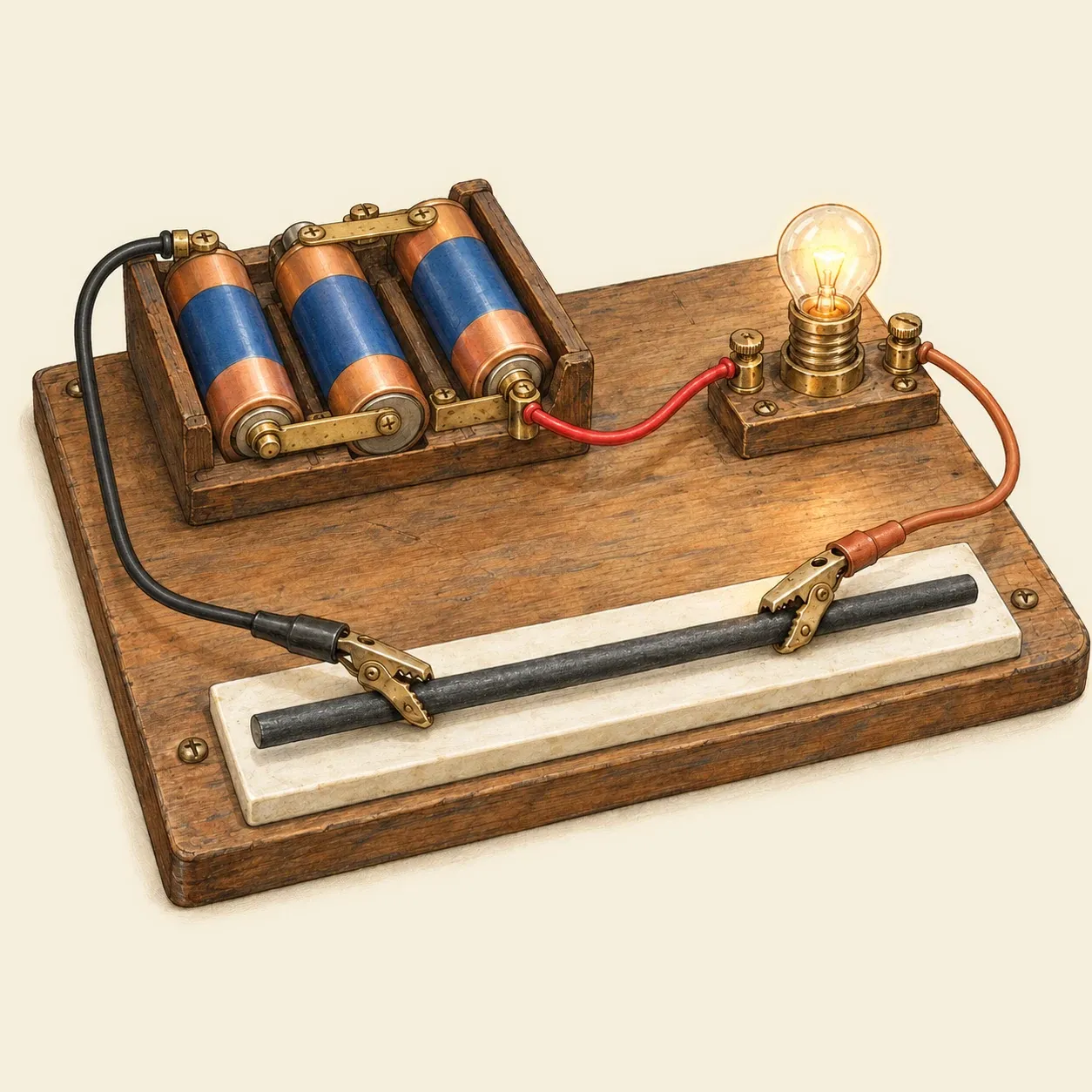 A pencil lead between two clips works as a rheostat: the farther apart the clips, the dimmer the bulb.
Graphite, the “lead” of a pencil, conducts far less well than copper, and a length of it makes a working rheostat for a small lamp. You need a holder with three AA cells, which gives 4.5 volts, a torch bulb rated for about that voltage in a holder, three wires with crocodile clips at both ends, and a thick lead for a mechanical pencil. A wooden pencil split lengthwise so its core is exposed along its whole length also works.
Lay the lead on a ceramic tile. Connect one terminal of the battery holder to the bulb, the bulb to a clip at one end of the lead, and the other battery terminal to the second clip. Touch the second clip to the lead close to the first: the bulb lights almost as brightly as when wired straight to the cells. Slide it along the lead and the bulb dims, because the current now has to cross a longer path of graphite. Note how far apart the clips are when the glow disappears. A length of resistance wire, sold for school experiments, gives the same result and lasts longer. Disconnect the bulb between trials so that it and the cells last.
Graphite is brittle and the clips can crush it, so close them gently. Use only small dry cells, never a car battery, a lithium pack or a mains adapter. The lead and the wire warm up, and with stronger supplies a spark can jump where a clip touches the graphite. Keep paper and other things that burn away from the tile. Never join the two battery terminals directly or through the clips alone: the wires heat quickly and the cells can leak.
History and evolution
In 1825 and 1826 Georg Simon Ohm passed current through wires of different lengths, thicknesses and metals and measured it with a magnetic needle placed beside the wire. In 1827 he published the relation between current, voltage and resistance in a book on the galvanic circuit, Die galvanische Kette, mathematisch bearbeitet.
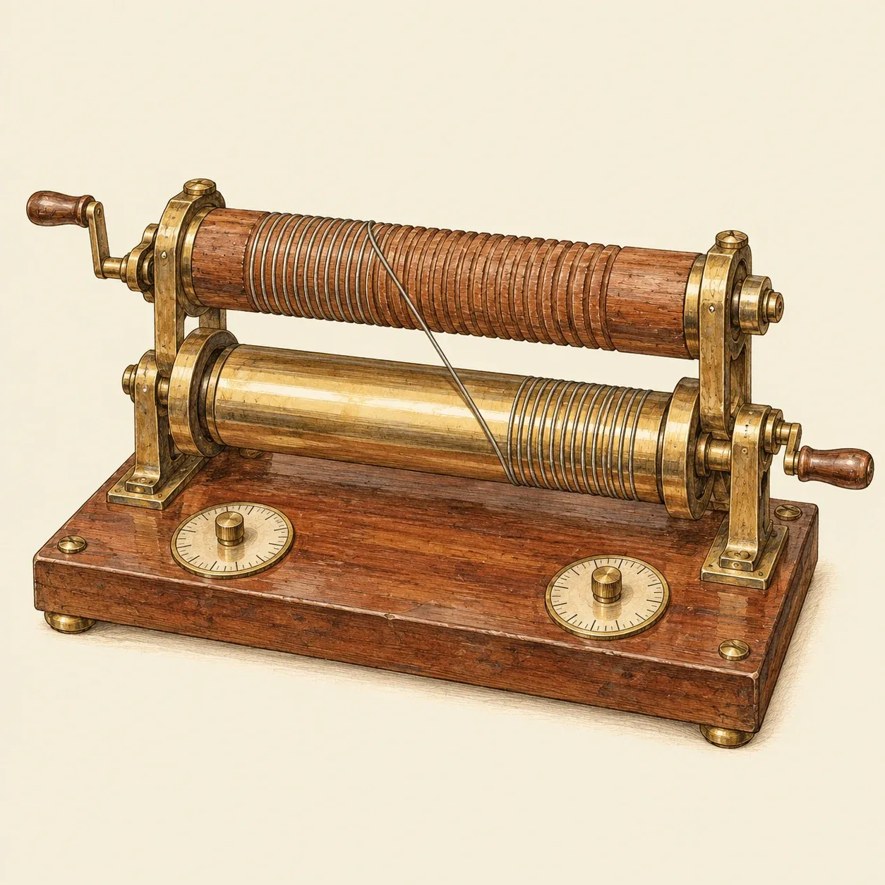 In Wheatstone’s two-cylinder rheostat, wire wound onto the wooden cylinder added resistance and wire on the brass one was short-circuited.
At the start of 1840 Moritz Jacobi showed the Academy of Sciences in St Petersburg an instrument for regulating the current from a battery. In August that year, in London, Charles Wheatstone showed him instruments of his own built on the same principle. Wheatstone described them in his Bakerian Lecture to the Royal Society in 1843 and named them rheostats. In one form a bare wire runs between a wooden cylinder and a brass one. Each turn wound onto the wood adds to the resistance, while turns on the brass are short-circuited by the metal. King’s College London keeps a single-cylinder rheostat of 1843, and the Museo Galileo in Florence a two-cylinder one made in Naples in 1865.
The telegraph and the undersea cables needed resistances that could be reproduced anywhere. In 1860 Werner Siemens proposed a unit based on a column of mercury one metre long and one square millimetre in section. A committee of the British Association, with William Thomson, James Clerk Maxwell and Fleeming Jenkin, issued its standard coils in February 1865: wire loosely wound in copper cans filled with paraffin wax. Their unit took the name of the ohm.
Rheostats then served the new electrical industry. In Milwaukee in 1901 Lynde Bradley built a rheostat of carbon discs to control the speed of electric motors, in which pressing the discs together lowers the resistance; in 1903 he and Stanton Allen founded the Compression Rheostat Company, renamed Allen-Bradley in 1909. Radio sets made small fixed resistors an article of mass production, and Allen-Bradley brought out hot-moulded carbon resistors in 1935. Carbon and metal film resistors, more stable over time, replaced carbon composition from the 1960s and 1970s.