Wired circuit board
Parts screwed to a board and joined by wires
Contents
- 1Baseboard
- 2Terminal strip with screw terminals
- 3Tuning coil
- 4Variable capacitor
- 5Crystal detector
- 6Connecting wire
A wired circuit board holds the parts of an electrical circuit on a rigid insulating board, with each part screwed down and each connection made by its own length of wire. An experimental radio receiver built on a mahogany base around 1905 survives in the Science Museum in London, and in the 1920s radio sets built this way were called breadboards; the Atwater Kent company of Philadelphia brought out seven such models in 1923. Printed circuits took over from the 1940s, but a working circuit can still be built by hand with a board, screws and wire.
What it is
A wired circuit board is a flat, rigid piece of insulating material that carries the parts of an electrical circuit, such as resistors, capacitors, coils and valves, and joins them with separate wires. Each part is screwed to the board. Its connections end at terminals, and a wire runs from one terminal to the next, held under a screw or soldered. In the 1920s this was the usual way to build a radio set, and because the board was a plank of wood the method was called breadboard construction.
A printed circuit board replaces the wires with strips of copper bonded to the board, all made at once. In an integrated circuit, the components and their connections are formed together on a single chip of silicon. A wired board needs neither process: a board, screws, wire and the parts themselves are enough, and any connection can be changed with a screwdriver or a soldering iron.
How it works
The board must not conduct electricity and must keep its shape. A radio magazine of 1926 asked for good wood so that the baseboard would not warp, and stiffened a wide board with cleats underneath. The parts stand on top of the board. In the Atwater Kent sets of 1923 the wires ran underneath it, out of sight. Many receivers also had an upright front panel carrying the tuning knobs and dials; the baseboard behind it held the coils, valves and terminals and supported the panel, and wires ran from the controls on the panel to their points on the board.
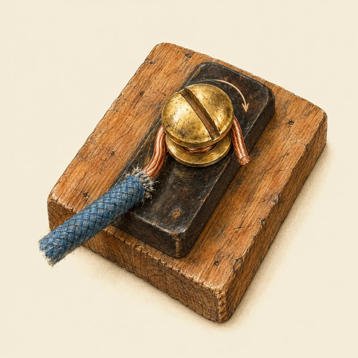 The hook goes round the screw in the direction it tightens, so tightening closes the loop.
Each terminal is a screw with a round head, or a binding post. A row of them on an insulating strip along the back edge, the terminal strip, takes the wires from outside the set: aerial, earth, headphones and batteries. To fasten a wire, the insulation is stripped from its end, the bare copper is bent into a hook, and the hook is laid under the screw head in the direction the screw turns as it tightens. Tightening then pulls the loop closed against the screw; a loop laid the other way is pushed out from under the head. A connection meant to last can be soldered instead.
The wiring follows the circuit diagram one connection at a time: every wire joins two points that the diagram shows as joined, and nothing else. Bare wires must never touch where the diagram has no connection, so they are kept apart, and insulated wire is used where two runs pass close together. Because each wire can be followed by eye, a fault can be traced and a part changed with a screwdriver. This made breadboard building popular with amateurs, who were always altering their sets.
How to do it
This board lights a torch bulb from three cells through a switch, and shows how parts are laid out and joined. You need a piece of dry plywood or softwood about 20 by 15 centimetres, a holder for three AA cells with two wire leads, a small bulb holder that screws down, a torch bulb rated for 4.5 volts, a strip of thin brass about 6 centimetres long, round-headed brass wood screws with washers, insulated single-core bell wire, a screwdriver, a bradawl and wire strippers. A crystal radio receiver is laid out on a board in the same way.
Draw the layout in pencil first: the cell holder at one end, the switch in the middle and the bulb holder at the other end, with the wires as straight lines parallel to the edges. Start every screw hole with the bradawl and screw the holders down. For the switch, drive one screw through a hole at one end of the brass strip and bend the strip so that its free end springs just above the head of a second screw; pressing it closes the circuit. Strip about a centimetre from each wire end and fasten it under a screw head as described above. Wire the circuit as a single loop: the positive lead of the cell holder to the screw that holds the brass strip, the second switch screw to one terminal of the bulb holder, and the other bulb terminal back to the negative lead.
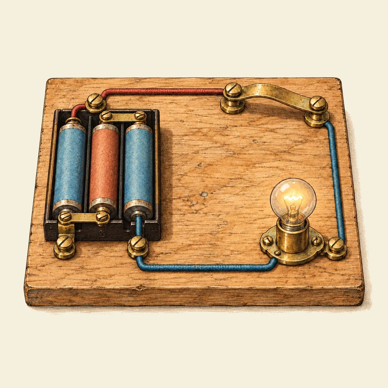 The finished board: cells, switch and bulb in one loop, every wire running straight between two screws.
Check the board before putting the cells in. Follow each wire with a finger and compare it with the drawing: there must be one unbroken path round the loop, and no bare copper may touch a wire or screw it is not meant to reach. Insert the cells and press the switch: the bulb lights. If it does not, check that every screw is tight and that the bulb is screwed fully into its holder. Once this works, a second bulb holder can be added beside the first and the new wiring traced again in the same way.
Use only ordinary dry cells. Never connect a board like this to the mains or to a car battery. A wire that joins the two leads of the cell holder directly makes a short circuit: the wire and the cells quickly grow hot and the cells can leak, so look for one before inserting the cells, and take the cells out when you have finished. The bulb becomes hot after a few minutes. Hold the board firmly and keep your other hand clear of the bradawl and the screwdriver. If you solder the joints, follow the precautions on the soldering iron page.
History and evolution
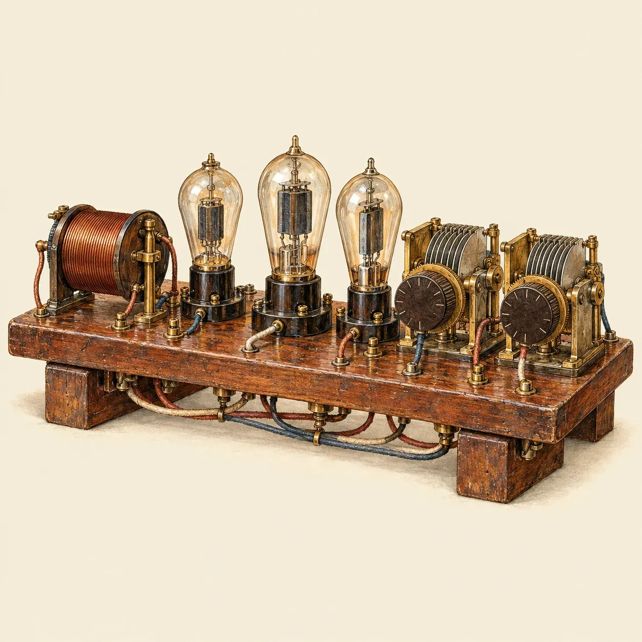 A breadboard receiver of the 1920s, with its wiring under the board.
Radio amateurs of the early twentieth century mounted their parts on a wooden base, and a bread cutting board from the hardware store was a ready source of a flat hardwood one. An experimental receiver that R. P. Howgrave-Graham designed and built around 1905, now in the Science Museum in London, has its parts on a mahogany base; an identical set appears in his book Wireless Telegraphy for Amateurs, whose British Library copy was received in May 1907. Makers sold sets built the same way: the 1913 edition of Alfred Morgan’s handbook for amateur wireless builders shows a receiving set by the Long Distance Wireless Company with its detector, tuning coil and condenser mounted on a mahogany base. A long-wave crystal receiver built in Edinburgh in 1913 by Alex Steuart to pick up the Paris time signals from the Eiffel Tower, now in National Museums Scotland, also has a mahogany base. By the 1920s a set built on a wooden board and wired by hand was known as a breadboard. The Roaring Twenties Antique Radio Museum keeps an Atwater Kent breadboard of 1922, and the Philadelphia firm brought out seven different breadboard models in 1923. They had no cabinet: the valves, coils, tuning capacitors and terminals stood on top of the board and the wiring ran underneath. The method made it easy to change a circuit, and it reached its peak in that decade. Many early cabinet radios were breadboard sets put inside a wooden box.
Wood gives no screening against radio waves, and early sets could squeal when a hand came near the front panel. When tuning capacitors with several sections on one shaft came in, screening between the stages became essential, and makers moved to a metal chassis, whose cut-outs could be standardised to speed up assembly. The parts were still joined one by one with hand-soldered wires.
In 1925 Charles Ducas applied in the United States for a patent on forming the connections of a circuit directly on an insulating support, by printing or stencilling a conductive paste and then plating it with metal. Paul Eisler, an Austrian engineer, settled in London in 1936 and began that year to experiment with printed circuits, making his first boards by screen printing. In 1942 he built a radio containing printed circuit boards, the first working device to use them, now held by the Science Museum in London, and he patented the method in 1943. The American arms industry put printed circuits into large-scale production during the Second World War, first in proximity fuzes for anti-aircraft fire. The integrated circuit later put the components themselves on a chip. Engineers still call the first trial version of a circuit a breadboard.