Centrifugal governor
Holding a machine's speed with spinning weights
Contents
- 1Drive pulley and bevel gears
- 2Arms crossed on a pin through the spindle
- 3Cast-iron balls
- 4Links and sliding collar
- 5Forked lever and rod
- 6Throttle valve in the steam pipe
A centrifugal governor keeps a machine close to a set speed. Two heavy balls on hinged arms spin with a shaft driven by the machine; when it runs too fast they swing out and rise, and a lever closes the valve, sluice or sails that feed it. Millwrights used it on windmills, where Thomas Mead patented one in 1787, before Boulton and Watt fitted it to steam engines in 1788.
What it is
A centrifugal governor is a speed regulator. A vertical spindle, turned by the machine, carries two heavy balls on arms hinged near its top. When the machine speeds up, the balls swing outwards and rise; when it slows down, they drop back. Through links, a sliding collar and a lever, that movement opens or closes whatever feeds the machine its energy: the steam valve of an engine, the sluice of a water wheel, or the sails of a windmill, whose area it can reduce. In flour mills a governor also had a separate job. Through a device called a lift-tenter it adjusted the gap between the millstones, and so the fineness of the flour, as the speed varied. That adjustment changes the grinding, not the power reaching the mill.
It works without anyone watching it. The governor measures the result, the speed, and corrects the cause, the supply, all the time. From 1788 Boulton and Watt fitted this type to their rotative steam engines: a strap from the flywheel shaft turns a pulley, a pair of bevel gears turns the spindle, and a lever from the collar works a throttle valve in the steam pipe.
How it works
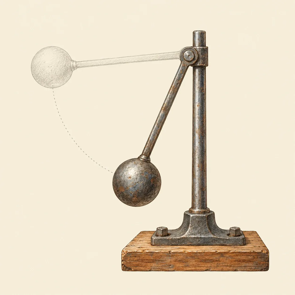 The faster the ball turns, the further out the arm leans and the higher the ball settles.
Each ball, swinging round on its arm, behaves like a pendulum moving in a circle. Its weight pulls it down, and the arm must pull it inwards to keep it on its circle. The faster it turns, the stronger that inward pull must be, and the arm can only give it by leaning further out. So for each speed there is one height at which the balls settle. W. J. M. Rankine gave the rule in 1869: at one turn per second the balls ride about 24.8 cm below the point where the lines of the arms meet the axis, and at two turns per second a quarter of that, 6.2 cm. The weight of the balls does not appear in the rule. Heavier balls settle at the same height and push the linkage with more force against friction.
In the Boulton and Watt governor, as John Farey described it in 1827, the two arms pass through a slot in the spindle and cross on one pin, like the blades of scissors. Above the pin, their short upper ends are bent outwards and joined by two short links to a collar that slides on the spindle and turns with it. When the balls fly out, the upper ends swing down and the links pull the collar down. The prongs of a forked lever ride in a groove round the collar without turning, and the lever passes the movement through a rod to the throttle valve. This valve is a thin disc on a spindle across the steam pipe: edgeways to the flow it lets the steam through, turned flat across it nearly closes the pipe. If the load on the engine drops and it speeds up, the balls rise, the valve closes partly and the engine slows. If the load grows, the balls fall and the valve opens.
A governor of this kind holds the speed within a band, not at one exact value. To keep the valve wider open under a heavy load, the balls must ride lower, and they only do so at a slightly lower speed; Rankine called such governors not truly isochronous. It also works best at low speeds. When the spindle turns fast, the balls are almost level with the hinge and a small change of speed hardly moves them. The governor can only correct a change of speed after it has happened, and Farey noted that each correction goes too far: after a sudden change of load, the speed swings to the other side a few times before it settles. If friction or a slow engine makes the governor respond late, the swings can grow instead of dying out. Engineers called this hunting.
How to do it
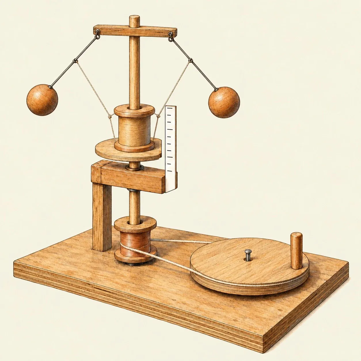 A hand-turned model: the faster the wheel turns, the higher the balls ride and the plate with them.
A wooden model shows the principle without an engine. Take a plywood board about 20 by 40 cm. Drill a hole near one end, and fix a wooden block with a matching hole on a post about 15 cm above it. You need a smooth dowel 10 mm thick and 45 cm long that turns freely upright in both holes, and two empty cotton reels that slide easily on it. Cut a round plate about 7 cm across from thin plywood, drill a 12 mm hole in its centre and glue it under one end of the first reel, with the holes in line. Thread this reel onto the dowel, plate downwards, and push the dowel down through the block, then thread the second reel onto the part below the block and push the end of the dowel into the hole in the board. Glue this lower reel to the dowel just above the board as a pulley. The upper reel stays loose above the block. Beside the pulley, mount a plywood disc about three times as wide as the reel, turning flat on a nail through its centre, with a wooden peg near its edge as a handle. Join the disc and the pulley with a loop of string tight enough not to slip.
Cut a strip of wood about 8 cm long and 2 cm square, and drill a 10 mm hole through its middle. Bend two arms of stiff steel wire, cut from a coat hanger, each with a small eye at one end. Slip the eye of one arm onto a small nail, then drive the nail into one long side of the strip, about 1 cm from an end and at right angles to its length, so that the eye is caught between the head and the wood. Drill a small pilot hole first so that the strip does not split, and leave the head a few millimetres proud so that the arm swings freely. Fix the second arm the same way near the other end, on the opposite side, then glue the strip across the top of the dowel, with the dowel in its hole. Each arm now hangs beside one end of the strip and can swing outwards, away from the dowel. Push each wire into a wooden ball 3 to 4 cm across and glue it, so that the centres of the balls sit about 15 cm below the nails. The two balls must weigh the same.
Tie a thread from the middle of each arm to the top rim of the loose reel, so that the reel hangs level, its plate just clear of the block, when the balls hang down. For the scale, cut a strip of card about 2 cm wide and as tall as the reel, and draw a line across it every 5 mm. Make the block long enough to reach just beyond the edge of the plate, and glue the lower end of the card upright against the end of the block, so that the card stands a few millimetres from the plate’s edge. As the reel rises, the rim of the plate moves up past the marks. The card is no taller than the reel, so it stays below the threads and the balls.
Turn the handle slowly, then faster. At low speed nothing moves, because the balls must lift the reel and its plate as well as their own weight. Past a certain speed they swing out, and the reel and its plate rise with them. The faster you turn, the higher they ride; slow down and they fall back. Tape two equal coins under the plate, on opposite sides of the dowel, and you have to turn faster to bring the rim of the plate to the same mark, as with a governor that carries a weight on its collar. On an engine, the height of the reel would set the opening of the valve.
History and evolution
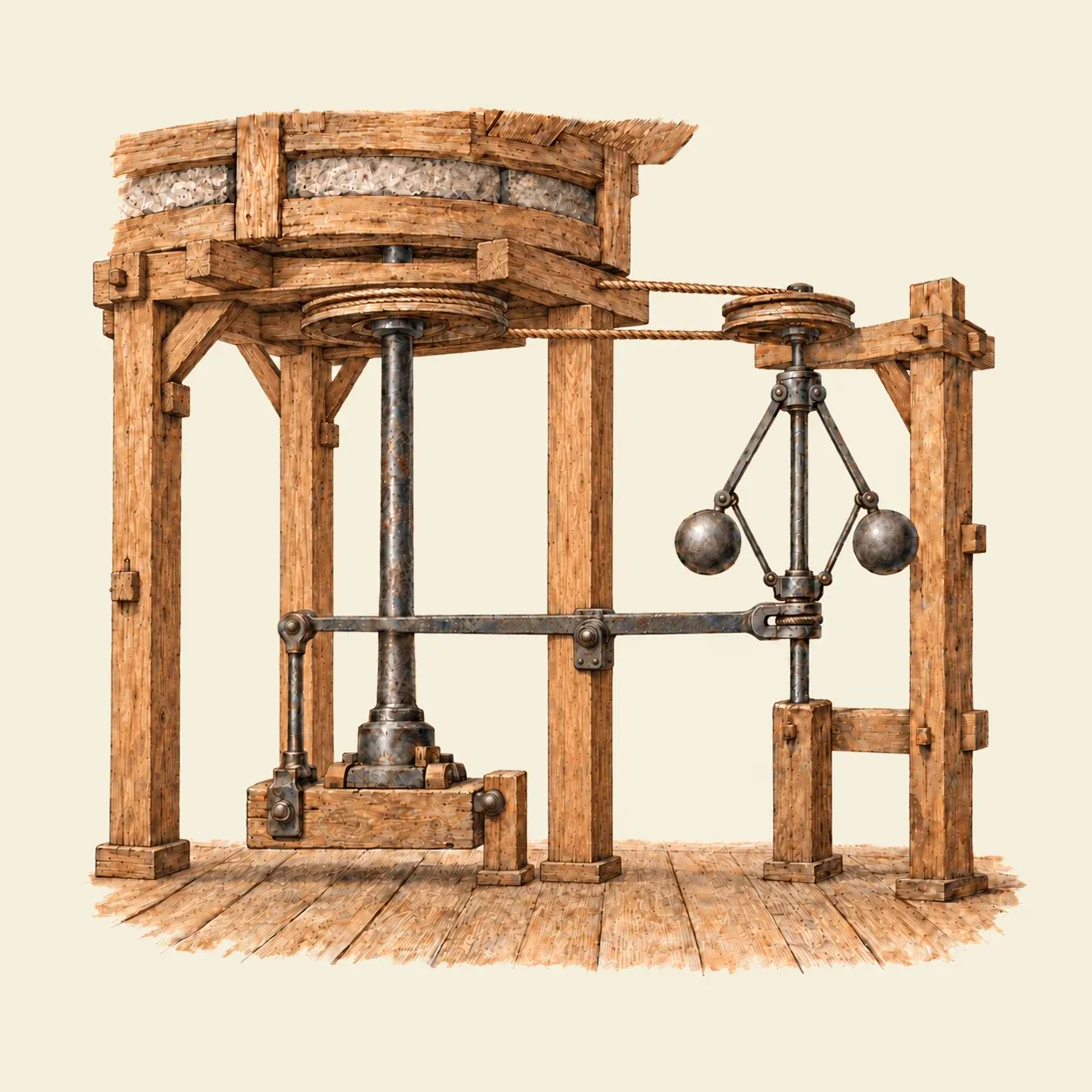 In a mill, the governor works a long iron lever, the steelyard, that sets the gap between the millstones.
Millers needed a steady speed long before steam engines did. A windmill speeds up and slows down with every gust, and the gap between the millstones, which decides how fine the flour is, changes with the speed. Too much speed can make the stones rub, which overheats the flour. British millwrights of the eighteenth century built lift-tenters, devices that adjusted the gap between the stones as the speed changed. The oldest dated one that measured the speed with spinning weights is in the patent of the English millwright Thomas Mead, in 1787. Otto Mayr, a historian of technology, describes two sets of whirling weights in it: one worked the lift-tenter, the other reduced the area of the sails when the mill ran too fast. Some engineering timelines and popular histories say mills used such governors from the seventeenth century, crediting Christiaan Huygens, but they cite no dated drawing or text. In later mills the governor stood on the floor below the stones and worked a long iron lever, the steelyard, linked to the beam that carries the stone spindle.
In May 1788 Matthew Boulton visited the Albion Mill in London, the steam-driven flour mill he and James Watt had built, and found a lift-tenter on its stones, probably fitted by the young millwright John Rennie. He described it to Watt. Watt drew a centrifugal speed regulator in November, and in December a governor for the Lap engine of Boulton’s Soho works in Birmingham. That engine is now in the Science Museum in London, which describes it as the first fitted with a governor. Watt did not claim the device as his invention, and the engineer John Farey wrote in 1827 that its principle had been used before in wind and water mills. Samuel Smiles, in his Lives of Boulton and Watt of 1865, still counted it among Watt’s inventions.
Engineers soon met the limits of the simple governor. In 1868 James Clerk Maxwell published On Governors, the first mathematical account of when a governed engine settles and when it hunts, now counted among the founding papers of control theory. From the 1850s, governors with a weight on the collar, such as the one Charles Porter patented in 1858, and then governors with springs could work at higher speeds. The same principle holds the speed of the water turbines that drive generators.