Line shaft
One engine, many machines, through shafts and belts
Contents
- 1Main driving pulley
- 2Line shaft and its coupling
- 3Hanger with bearing and drip oiler
- 4Flat leather belt to the countershaft
- 5Fast and loose pulleys with the belt-shifting fork
- 6Stepped pulleys of the pillar drill
A line shaft is a long rotating shaft that carries the power of one engine to many machines. Hung under the ceiling of a mill or workshop, it drives each machine through pulleys and flat belts, so that a single water wheel, steam engine or electric motor can work a whole room. A wall painting of 1167 in the Yanshan temple, in northern China, shows one water wheel whose long axle works both trip hammers and a mill. In Europe, the silk mill built about 1721 at Derby on the Italian model ran the machines of five floors from one water wheel.
What it is
A line shaft is a long rotating shaft that carries the power of one engine to many machines. It runs along the ceiling of a mill or workshop, held in bearings, and carries a row of pulleys. Flat belts run from these pulleys down to the machines, or to shorter shafts that drive them, so that a single water wheel, steam engine or, later, electric motor can work every machine in a room, or in a building of several floors.
Until late in the 19th century most factories worked this way. A typical plant had an iron or steel line shaft about 3 inches (7.6 cm) thick running the whole length of each floor, with countershafts hung parallel to it, from which each lathe, drill or loom took its drive. The machines therefore stood in rows under the shafts, with belts running up from every one of them to the shafting overhead.
How it works
The prime mover drives the main pulley at one end of the line shaft, through a belt or through gears. The shaft is made of lengths of iron or steel joined by couplings, and it hangs from the ceiling beams in cast-iron brackets called hangers, each holding a bearing. A drip oiler above each bearing kept it supplied with oil, and the machine operators usually filled and adjusted the oilers every day. Pulleys fixed to the line shaft pass the power on to countershafts, shorter shafts hung parallel to it, and from these to the machines.
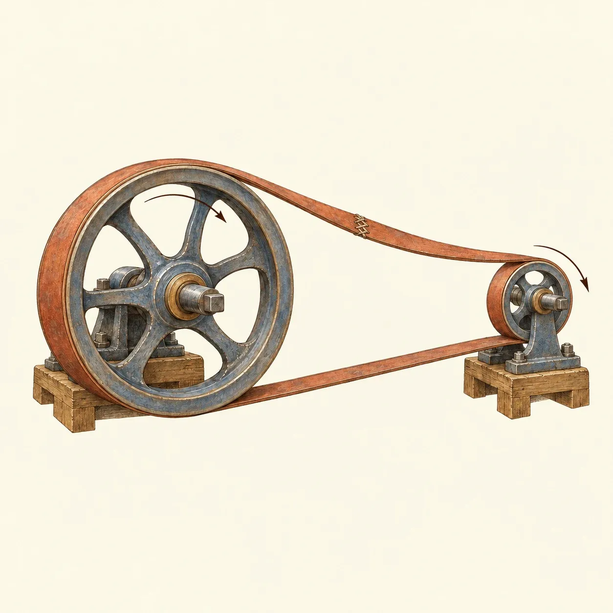 The small pulley turns three times as fast as the large one; the run of the belt being pulled is taut, the other sags.
A flat belt drives by friction. Wrapped round two pulleys and pulled tight, it grips their rims, and the run being pulled by the driving pulley is taut while the other is slack. The belt moves at the same speed over both rims, so a small pulley turns faster than a large one in proportion to their diameters: a pulley one third the size of the one driving it turns three times as fast. Stepped pulleys on the countershaft and on the machine let the worker change speed by moving the belt to another pair of steps. The rims are made slightly convex, and a flat belt climbs to the highest point of the curve and stays there. In his treatise on millwork of 1863, the Manchester millwright William Fairbairn gave belt speeds of 25 to 30 feet (about 8 to 9 m) per second.
The whole network turned from the moment the engine started in the morning until it stopped at night. To start or stop one machine, its countershaft carried two pulleys of the same size side by side: a fast pulley keyed to the shaft and a loose pulley turning freely on it. With the belt on the loose pulley the machine stood still. A fork worked by a lever pushed the belt across onto the fast pulley, and the machine started. Fairbairn notes that the fork must act on the run of the belt that is moving onto the pulleys, and that the belt slips at first, bringing the machine up to speed without a shock.
Friction in all those bearings and belts used up part of the power, even when only a few machines were working. If the engine or a line shaft broke down, a whole room or even a whole factory stopped until it was repaired. Belts stretched and had to be shortened and laced together again. In buildings of several floors, belts passed through holes in the floors that let fire spread, and they were often enclosed in costly belt towers.
How to do it
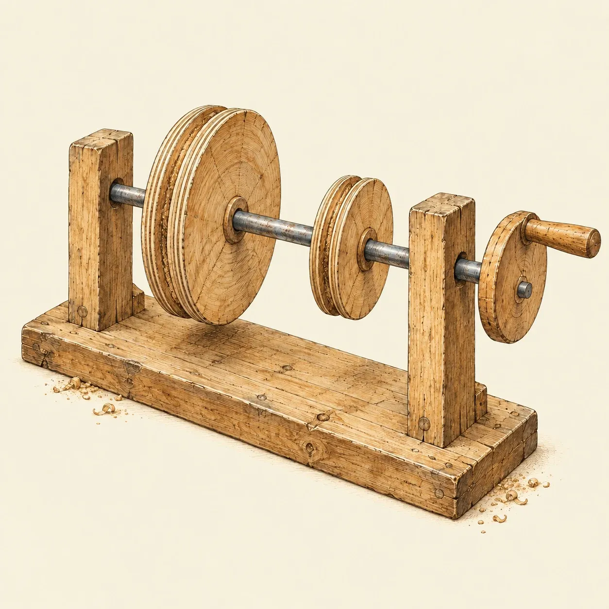 The model’s line shaft: a rod turning in two uprights, worked by a crank.
A small tabletop model shows the whole system and runs by hand. On a board about 60 cm long, fix two hardwood uprights about 30 cm high. Drill each near the top so that a steel rod 6 to 8 mm thick, or a hardwood dowel, turns freely in the holes; a little candle wax helps. This is the line shaft. Fit a crank at one end: a wooden disc glued to the rod, with a peg as a handle.
Cut pulleys from plywood with a hole saw, in two or three sizes, and glue them to the shaft. Sand each rim slightly round, highest in the middle, or wrap a narrow band of tape round its centre. Make the belts from strips of cotton tape sewn into loops, or from wide rubber bands, tight enough to grip without bending the shaft.
Below the shaft, mount two short spindles in small wooden blocks on the board, parallel to the shaft. On the first, glue a small pulley and a card disc painted in coloured sectors, so that you can see it spin. On the second, glue one pulley, the fast pulley, and beside it slide a second pulley of the same size that turns freely, held in place by a washer. Give this spindle a small wooden cam that lifts a little hinged hammer and lets it drop. Bend a stiff wire into a fork that straddles the belt just before it reaches the pulleys, and fix it to a stick pivoted on the board, so that moving the stick shifts the belt from one pulley to the other.
Turn the crank and count: a small pulley driven by one three times its size turns three times for each turn of the shaft. Move the belt onto the loose pulley and the hammer stops while the shaft keeps turning; move it back and the hammer works again.
Even a slow model can pinch. The danger is where a belt runs onto a pulley, which draws in fingers, hair, loose sleeves, cords and jewellery. Tie back long hair, roll up your sleeves, keep your fingers away from belts and pulleys while the shaft turns, and shift belts only with the fork. Stop the crank and wait until everything stands still before you adjust anything. Drive the model by hand only, never with a drill, a mains motor or an engine, and supervise children. Real line shafts, in museums or old workshops, can maim or kill: stay behind the barriers and never touch a running belt.
History and evolution
A wall painting in the Yanshan temple at Fanshi, in Shanxi, finished in 1167 under the Jin dynasty by the painters Wang Kui, Wang Dao and others, shows a mill beside a stream. A single large vertical water wheel turns a long wooden axle that lifts trip hammers hulling grain in a thatched shed on the lower level, and also drives a millstone on the floor above. Gao Ce and Xu Yanhong, who studied the painting on site, read the drive to the millstone as two gear wheels set at right angles; Shi Xiaolei agrees that one wheel drives both the hammers and the mill, but questions their reading of how the mill is built.
In his treatise on agriculture, whose preface is dated 1313, the Chinese official Wang Zhen described a mill for fast, plentiful water. Its wheel was tall and wide, and its axle, as thick as a man can embrace, was made as long as needed. Three gear wheels along the axle each drove a large millstone with wooden teeth round its edge, and each of these drove two more, so that the one wheel turned nine millstones. The gear wheel at the head of the axle also struck a lower shaft that worked several trip hammers. Wang Zhen had seen such mills in Jiangxi and elsewhere, grinding tea: the hammers pounded the leaves before they went to the stones.
In Italy, Mario Grassi dates to the late 16th century the Bolognese silk mills in which one water wheel drove the throwing and winding machines through a common shaft. The silk mill at Derby, in England, was a copy of these Italian mills. An earlier water-powered mill with Dutch machines, built for Thomas Cotchett on an island in the Derwent, had failed. John Lombe, who had worked for Cotchett, brought back from Italy drawings of the Piedmontese throwing machines and a group of Italian workmen, and on the same site his half-brother Thomas, who received a patent in 1718, built a new mill with him.
The Derwent Valley Mills World Heritage Site says that work began in 1721, while the Derbyshire Historic Environment Record quotes both 1718 to 1722 and 1717 to 1721 for its construction. The mill stood five storeys high on stone arches, and all its machines took their power from a single undershot water wheel. William Hutton, who had served a seven-year apprenticeship there, wrote in 1791 that the wheel turned about twice a minute. He added that any one of the many parts could be stopped and taken out of gear at will, yet the whole, spread through five large rooms, was a single machine that moved and stopped together.
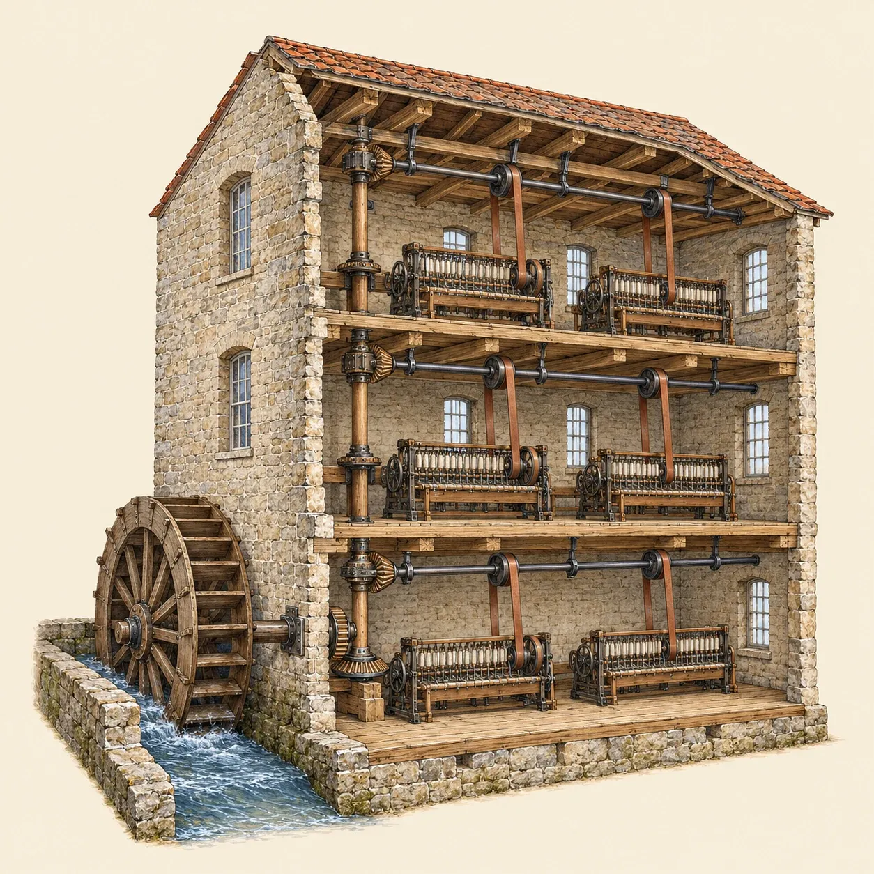 In gear-driven mills an upright shaft carried the power up the building to a shaft on each floor.
In British and early American mills the power went from the wheel up a vertical shaft and through gears to an overhead shaft on each floor. At the beginning of the 19th century, Fairbairn recalled, these shafts were heavy and slow, square, made of cast iron and badly coupled, and in some mills it took almost as much power to turn them as to drive the machinery. After he went into partnership with James Lillie in Manchester in 1817, the two millwrights replaced them with light wrought-iron shafts running three times as fast, which saved both iron and power. By his reckoning, a shaft turning at 50 revolutions a minute needed about three times the weight of a faster one to carry the same work.
In American mills, belts came to replace much of the gearing. By the middle of the century they were a mark of American mills, and in 1863 Fairbairn wrote that the Americans preferred leather straps and large pulleys. In some American cotton mills a great drum on the main drive sent the power through belts two to three feet (about 60 to 90 cm) wide to the lines of shafting, so that the whole mill ran without gearing. Lancashire and Yorkshire millwrights kept gearing and light, fast shafts, and used straps mainly to carry the power from the shafts to the machines. Fairbairn granted that belts ran smoothly and quietly, but held that they lost more power to friction in the journals and needed frequent repair.
Electric motors at first simply took the place of the steam engine at the end of the same long shafts. The engineer H. C. Spaulding pointed to the friction losses and to the waste of turning all the shafting however few machines were in use. Factories then split the shafting into groups, each with its own motor. At the General Electric works in Schenectady, 43 motors turned 5,260 feet (about 1,600 m) of shafting in some 40 shops. Shafts grew shorter, 30 to 50 feet (9 to 15 m) in many machine shops, and then disappeared as each machine received its own motor. In 1929, according to Warren Devine, electric motors made up about 78% of the capacity for driving machinery in American manufacturing.