Plain bearing
A shaft turning on a film of lubricant
Contents
- 1Journal of the shaft
- 2Cast-iron pedestal
- 3Cap and cap bolt
- 4Bronze half-shell
- 5White-metal lining
- 6Oil cup and oil hole
A plain bearing supports a turning shaft by letting it slide in a close-fitting hole, with grease or oil between the surfaces. At speed the shaft can ride on a thin film of oil without touching the bearing at all. The oldest evidence comes from potters of the Ubaid period in Mesopotamia, whose turntables rotated on a peg in the fifth millennium BCE.
What it is
A plain bearing holds a shaft in place and lets it turn. The part of the shaft that runs in the bearing is called the journal. It turns in a hole that is very slightly larger, lined with a material that slides well, and grease or oil fills the narrow gap. Nothing rolls: the surfaces simply slide past each other, which is the difference from a ball bearing.
Plain bearings are everywhere. A door that turns on a peg set in a stone socket has one, as does a cart wheel turning on its greased axle (wheel) or the crankshaft of an engine turning in its bronze or white-metal bearings.
In a plummer block of the nineteenth century, the kind that carried the shafts of engines and mills, a cast-iron pedestal is bolted to a stone, and a cap is held down on it by two bolts. Between them sit two half-shells of bronze, the brasses, lined with a soft white metal, and an oil cup on top feeds the journal through a hole. Because the bearing comes apart at the level of the shaft, worn shells can be replaced, and the cap can be tightened to take up wear.
How it works
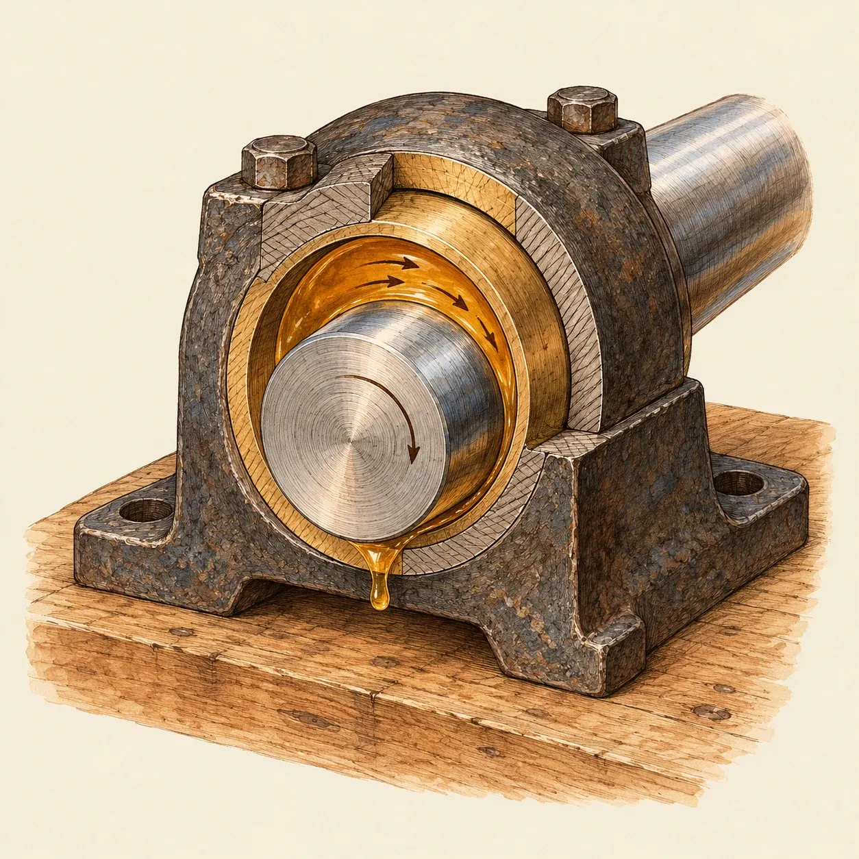 The turning journal drags oil into the narrowing gap, where the pressure rises enough to hold the shaft up.
The journal needs room to turn and a gap for the lubricant. For bearings lined with white metal, a design guide gives a clearance across the diameter of half to one thousandth of the diameter, and a common workshop rule is one thousandth: a shaft of 50 mm runs in a hole about 0.05 mm larger. Too little clearance and the bearing runs hot. Too much lowers the load the oil can carry and lets the shaft vibrate.
At rest, the shaft lies on the bottom of the bearing, separated from it only by a thin layer of lubricant that clings to both surfaces. When it starts to turn, the surfaces rub against each other through that layer. As the speed rises, the turning journal drags oil with it into the part of the gap that narrows towards the loaded side. The oil cannot escape quickly enough, its pressure rises, and it lifts the journal, which then floats slightly off centre on a thin film of oil. From then on, the only friction left is the resistance of the oil to being sheared.
The lining is softer than the shaft on purpose. A bearing maker’s guide describes white metal, a soft alloy of tin with a little antimony and copper, as taking the brunt of any damage instead of the more costly shaft: small grains of dirt sink into it rather than score the journal. Bronze stands higher temperatures but accepts dirt less well.
How to do it
Two split bearings in hardwood carrying a steel rod show how clearance, lubrication and wear take-up work. Turn the rod by hand only.
Make the blocks. For each bearing, cut two blocks of a close-grained hardwood such as beech or oak, about 8 cm long, 5 cm wide and 3 cm thick, and plane the faces that will meet until they lie flat on each other. Put a strip of thin card between them as a shim, clamp the pair tightly in a vice, and bore a hole straight through along the joint line, the size of the rod, for example 12 mm. Mark each pair so it goes back together the same way.
Add the oil way. In the upper block, drill a small hole from the top down into the bore and cut a shallow groove along the top of the bore with a round file. Drill two holes through both blocks, one on each side of the bore, for bolts or long screws that will hold the cap down.
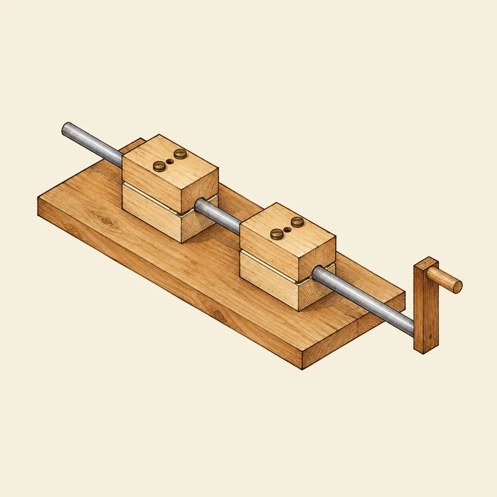 Two split bearings of hardwood on a board carry a steel rod turned by a wooden crank.
Assemble. Screw the two lower blocks to a board in line with each other, lay a smooth steel rod in them, and bolt the caps on with the card shims in place. Fit a wooden crank to one end of the rod.
Test. Turn the rod dry and feel the effort and the warmth after a minute. Then put a few drops of light machine oil into each oil hole and turn again: it runs smoother and cooler. Remove the shims and tighten the caps a little at a time until the rod binds, then slacken them until it turns freely without rattling. This is how a worn bearing is taken up.
History and evolution
A survey of the Ubaid culture of Mesopotamia by EBSCO describes its pots as made on a turntable whose top rotated on a peg, and Alev Erarslan places the arrival of this slow wheel in the final phase of the period, Ubaid 4, which Luca Volpi dates to about 4800–4400 BCE in southern Mesopotamia. Some Ubaid pottery, made between about 5900 and 4600 BCE, carries painted bands so even that Johnny Baldi and Valentine Roux conclude the pot was turning on a pivot under a still hand. They also describe a clay disc about 26 cm across, with a slight socket on its underside, from a late Ubaid potter’s workshop of about 4700 BCE at Tell Feres al-Sharqi in north-eastern Syria, and suggest it turned on a pivot as a turntable.
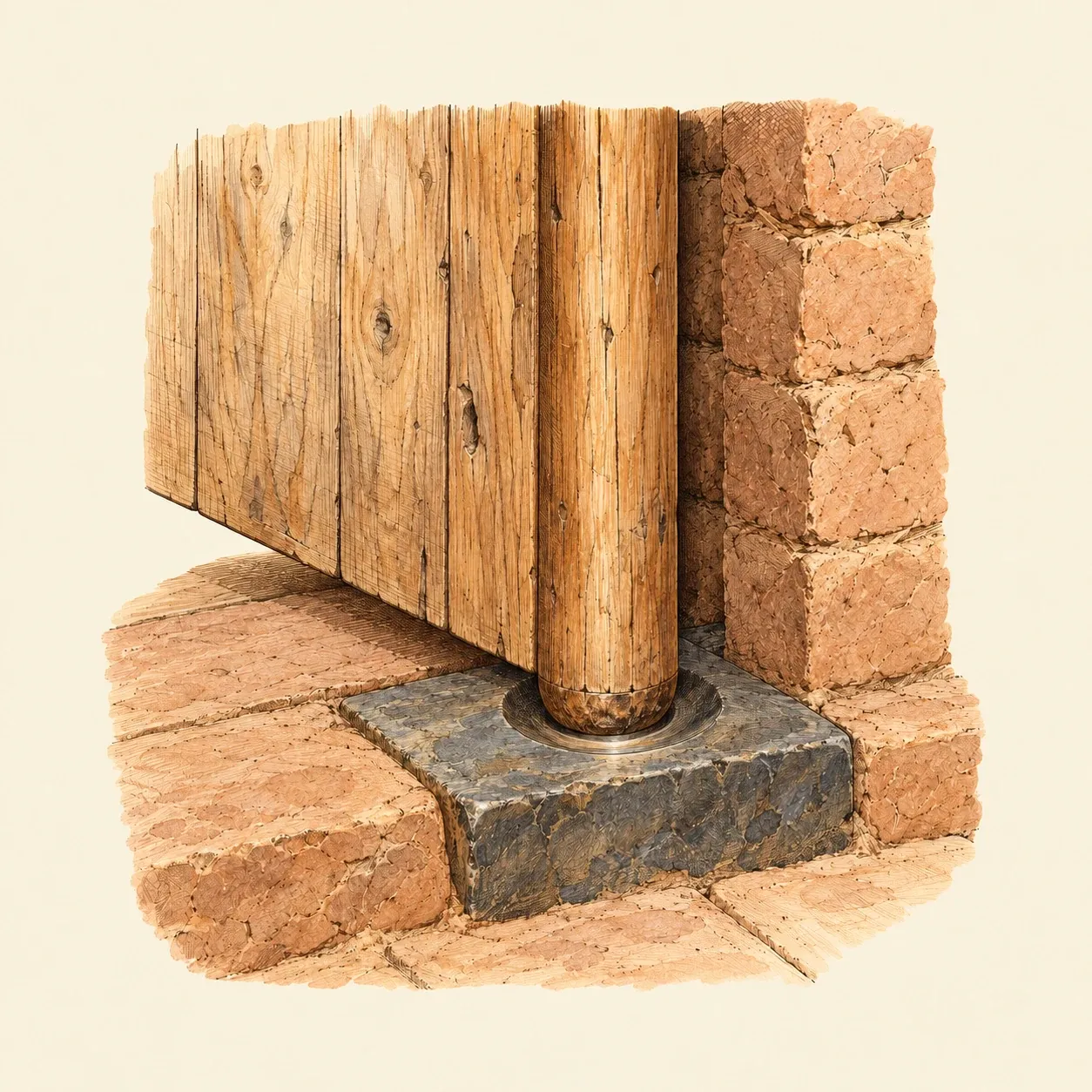 The door turns on a pivot set in a polished hollow in the stone.
Doors turned the same way. An Egyptian door had a pivot at the top and the bottom of its hanging edge, the upper one in a hole in the lintel and the lower one in a socket in the floor; on a floor of mud brick, a stone was set to take the weight and the wear. A stone socket of 3000–2800 BCE, found in place at the entrance of the temple of Hierakonpolis, is now in the Penn Museum. Enrico Ciulli, summarising Duncan Dowson’s history of tribology, notes that such sockets were lubricated with bitumen or animal fat. Wheels on axles, from the fourth millennium BCE, ran in the same kind of bearing. A deposit on the axle of a chariot from an Egyptian tomb of about 1400 BCE was analysed in the twentieth century as animal fat with sand and compounds of lime.
For centuries bearings were made of wood, stone, bronze or brass, greased with tallow or oiled. Engine builders of the late eighteenth century set the journals of their shafts in two brasses fitted into a cast-iron box, with a cap held by two screws that could be tightened as the brasses wore, as John Farey described in 1827.
In July 1839 Isaac Babbitt, of Boston, patented a way of lining bearing boxes with a soft metal; his example was fifty parts of tin to five of antimony and one of copper. The idea spread, and in Britain such alloys are called white metal. In 1854 John Penn and Francis Pettit Smith patented a stern bearing for screw propeller shafts made of lignum vitae, a dense tropical wood, lubricated by the sea water around it.
In the early 1880s Beauchamp Tower, working for a friction committee of the Institution of Mechanical Engineers, ran a test journal under a load of about 100 lb per square inch (about 7 bar). When a hole was drilled in the top of the bearing, oil rose through it and forced out the plugs put in it, and gauges showed a pressure there well above the average load. In 1886 Osborne Reynolds published the theory of the oil film that explained Tower’s results, and bearing design still rests on his equation.