Gyroscope
A spinning rotor that holds its direction
Contents
- 1Ivory ball (the rotor) with its equator line
- 2Drum on the axle and silk thread
- 3Inner ring carrying the axle of the ball
- 4Middle ring, pivoting at right angles
- 5Outer ring fixed on the wooden stand
- 6Screw pivot with a steel point
A gyroscope is a fast-spinning rotor held in rings that pivot at right angles, so that its axle can point in any direction. While it spins, the axle keeps its direction in space however the stand is moved, and a push on it makes it swing sideways. The oldest known example is the Machine made for Johann Bohnenberger at Tübingen by 1810; Léon Foucault named the instrument in 1852.
What it is
A gyroscope is a heavy rotor that spins fast on an axle, mounted in a set of rings called gimbals. The axle turns in pivots on an inner ring. The inner ring pivots in a second ring about an axis at right angles to the axle, and the second ring pivots in a fixed outer ring about a third axis. All these axes meet at the centre of the rotor, so the axle can take any direction, and the outer ring can be turned or carried about without twisting the rotor.
The first known instrument of this kind was made at Tübingen for the astronomer Johann Gottlieb Friedrich Bohnenberger, who called it simply the Machine. The example now in the town museum is 16.2 cm tall. An ivory ball, slightly flattened at the poles and marked with an equator, stands for the Earth and turns in the smallest of three brass rings. The outer ring is fixed on a turned wooden stand, and a silk thread wound on a small drum on the axle and pulled hard sets the ball spinning. Bohnenberger used it in his lectures to show how the Earth’s axis keeps its direction and how it slowly wanders. Gyroscopes now help to steer ships, aircraft and spacecraft, and tiny micromechanical versions sense how a phone is turned.
How it works
A spinning body has angular momentum, a quantity that grows with the mass of the rotor, with how far that mass lies from the axle and with the speed of rotation, and that points along the axle. It changes only when a torque acts on the rotor. In gimbals that balance at the centre, gravity and the movements of the stand exert almost no torque on the rotor, so the axle keeps the direction it had at the start. Bohnenberger wrote that one could carry the Machine about in any direction and at any speed, and that its axis would stay parallel to itself, pointing north like a compass needle if it had been set that way.
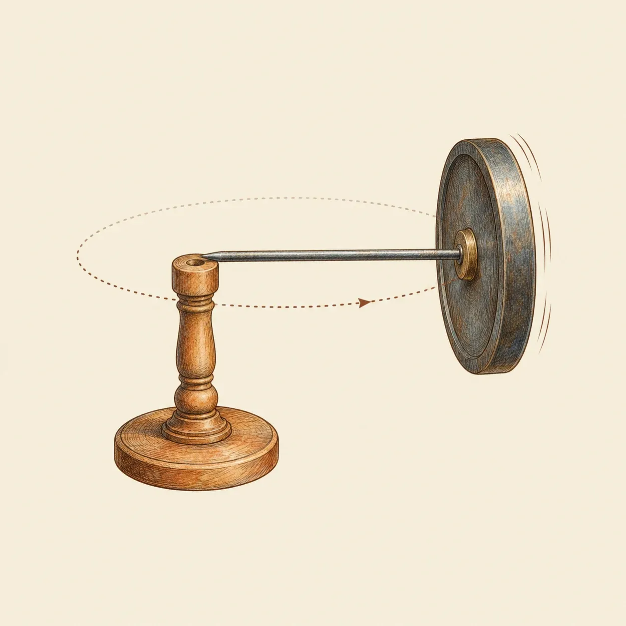 Held at one end only, the spinning wheel does not fall: its axle travels slowly round the post.
When a torque does act, the rotor does not tip the way it is pushed. Its axle moves at right angles to the push, a motion called precession. Hang a small weight on one side of the inner ring and, instead of dropping, that side travels slowly round in a horizontal circle. Bohnenberger added such a weight to imitate the precession of the Earth’s axis, which takes about 26,000 years to go round once. The faster the rotor spins, the slower the precession, so as the rotor runs down the precession speeds up.
No real gyroscope keeps its direction for ever. Friction in the pivots, a rotor slightly out of balance and the drag of the air all apply small torques, so the axis drifts while the rotor slows. The engineer Jörg Wagner notes that friction in the gimbal bearings limits how long the axis keeps its alignment, which is why instruments that must work for hours are corrected by another sensor: an artificial horizon by levelling devices, a directional gyro by a magnetic compass. The Earth also turns beneath a gyroscope. Its axis holds its direction in space, so seen from the room it seems to turn slowly, and this is what Foucault set out to observe.
How to do it
For the rotor, use a metal disc 8 to 10 cm across and heavy at the rim, such as a small cast-iron pulley or a stack of large steel washers, clamped between two nuts on a steel rod about 5 mm thick and 12 cm long. Centre the disc exactly and tighten the nuts hard. File both ends of the rod to a blunt cone. Spin the rod between your fingertips: if the disc wobbles, or always stops with the same point at the bottom, it is off centre or out of balance, and it must be corrected before you go on.
Make three rectangular frames from hardwood strips or aluminium flat bar, each large enough to turn freely inside the next. Drill the inner frame on two opposite sides and drive a screw through each hole, with a small conical dimple drilled in its tip to take the end of the rod. Turn the screws until the rotor spins freely without play, and lock them with nuts. Hang the inner frame in the middle frame on two pointed screws set at right angles to the rod, and the middle frame in the outer frame on a third pair at right angles to both. Fix the outer frame upright on a heavy wooden base. All three axes must pass through the centre of the disc. With the rotor still, the inner frame should stay in whatever position you leave it; if one side always drops, add a little weight to the other side.
Wind a thin, strong cord round the rod between the disc and the frame, hold the base down and pull the cord quickly and steadily. Then lift the base and turn it: the axle keeps pointing the same way while the frames move round it. Press gently on the inner frame with a pencil and it moves at right angles to the push. Tape a coin to one side of the inner frame and watch that side circle instead of falling, faster and faster as the rotor slows.
A spinning disc can bruise or cut fingers, catch long hair, loose sleeves and cords, and fly off if it comes loose. Wear safety glasses, tie back long hair, keep your face out of the plane of the disc and check that the nuts are tight before each spin. Spin it only by hand with the cord, never with a drill or a motor, and let it run down by itself without grabbing it.
History and evolution
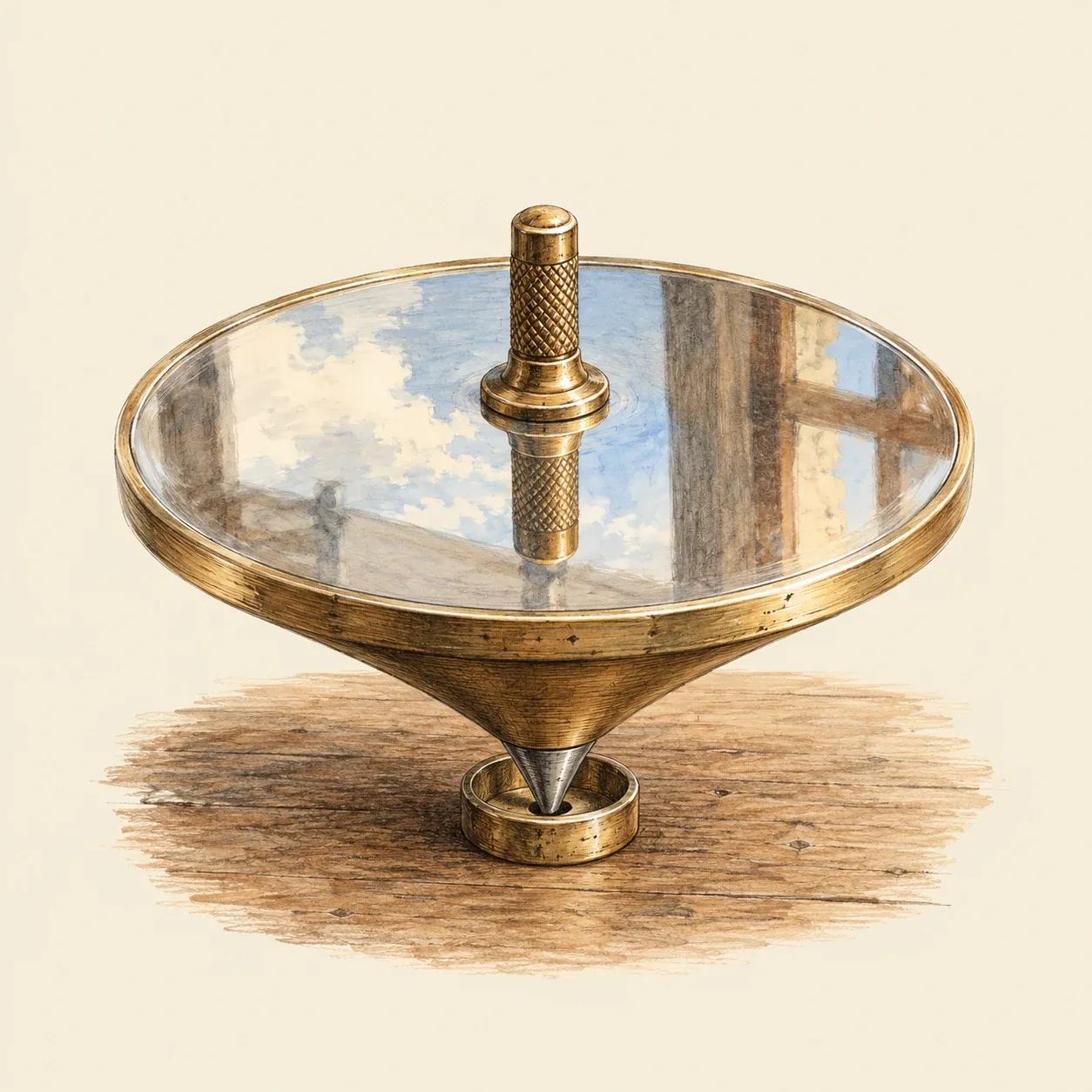 A top whose upper face is a polished mirror stays level and can serve as an artificial horizon.
A spinning top served as an instrument before the gimbal mount. In 1743 the English sea captain John Serson tried a top whose upper face was a polished mirror. It stayed level on a rolling ship and gave an artificial horizon for measuring the height of the sun when fog hid the sea’s horizon, a problem of celestial navigation. Serson was lost at sea on HMS Victory in 1744.
The rotor in gimbals appears at Tübingen. Johann Friedrich Benzenberg, an astronomer from Düsseldorf, visited Bohnenberger in December 1810 and described the instrument in his travel letters, printed in 1812, as something quite new. The oldest known drawing of it, on the cover of one of Bohnenberger’s manuscripts, dates from about the same time. On his way home Benzenberg showed the machine to Karl Theodor von Dalberg, who carried the news to Paris in the summer of 1811. Pierre-Simon Laplace brought it into the École polytechnique, which received two examples from Tübingen. Bohnenberger published his own description only in 1817. The university mechanic Johann Wilhelm Gottlob Buzengeiger made the machines, with a rotor of wood filled with lead or, at twice the price, of ivory. One of his originals was found in December 2004 at the Kepler-Gymnasium in Tübingen, and a second, almost identical, came up at an online auction in 2010.
The instrument spread quickly, above all in France, where Laplace recommended it for teaching the precession of the equinoxes. In Philadelphia, Walter R. Johnson described in 1832 his “rotascope”, a spinning wheel in rings for showing the laws of rotation. He mentioned a small apparatus attributed to Laplace, made in France and copied by a local mechanic, with two rings at right angles and a small sphere loaded at one pole.
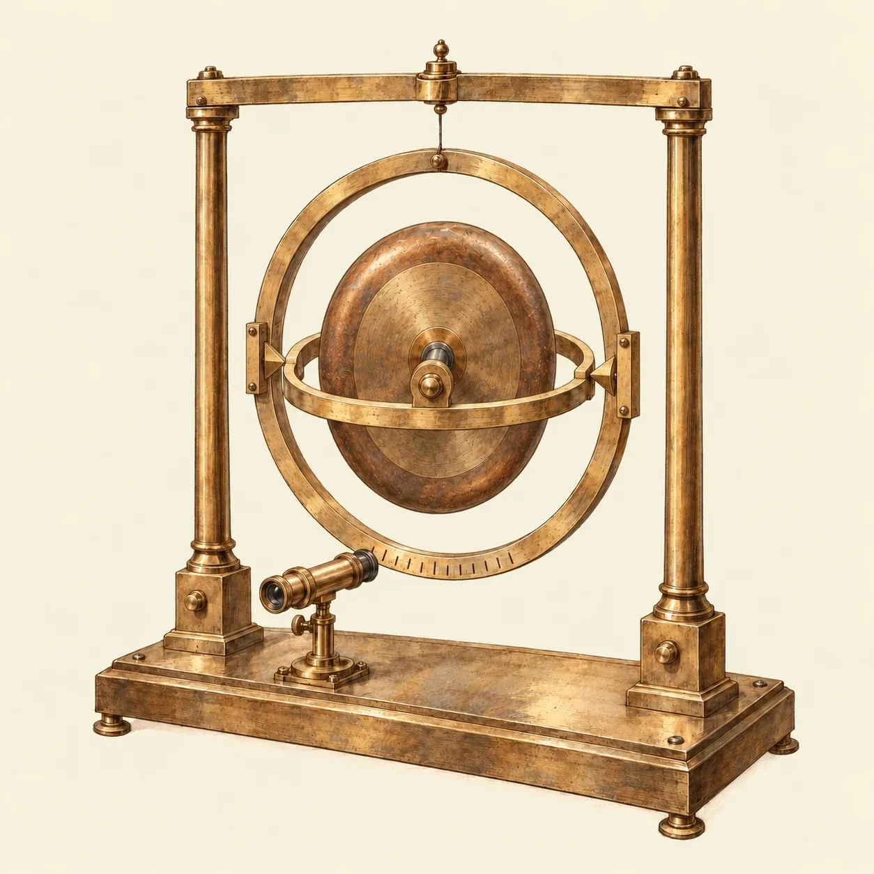 Foucault’s gyroscope of 1852: a microscope reads the slow turning of the rings caused by the Earth’s rotation.
Léon Foucault named the instrument in 1852, from the Greek for rotation and for observing. After showing the Earth’s rotation with his pendulum in 1851, he wanted a more direct proof. The gyroscope that Gustave Froment built for him had a heavy ring-shaped rotor in two gimbals. A crank and four stages of gears launched it at up to 200 turns per second, and it kept spinning for about ten minutes, long enough to follow through a microscope the slow drift of the axis against the turning Earth. Others were racing to do the same experiment. Foucault also found that by restraining the movement of one gimbal, the instrument could be made to sense one particular component of rotation.
That idea led to the gyrocompass, which seeks true north by sensing the rotation of the Earth. The company of Hermann Anschütz-Kaempfe in Kiel had one that passed sea trials on the German flagship Deutschland in 1908, and Elmer Sperry’s compass was ready for trials at sea in the United States by January 1911. From the First World War onward gyroscopes gave the pilots of aircraft an artificial horizon for flying in cloud and at night. During the Second World War gimballed platforms carrying gyroscopes and accelerometers became the first inertial navigation systems, built for the German A4 rocket. The most precise gyroscopes ever made flew on the satellite Gravity Probe B, which gathered data until 2005. Its final results, published in 2011, confirmed that the Earth’s rotation drags a gyroscope along very slightly, as general relativity predicts.